15
Fig. 26
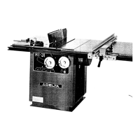
Fig. 23
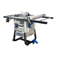
Fig. 24
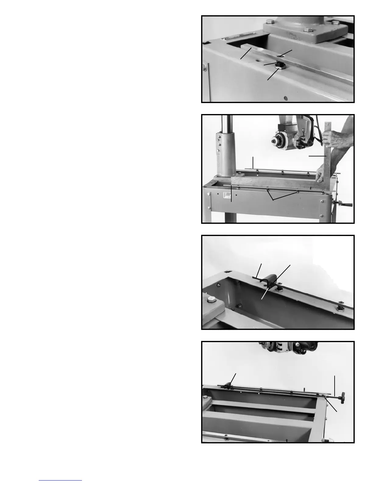
Fig. 25
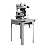
7. If an adjustment is necessary, remove screw (R)
Fig. 23, loosen locknut (S) and turn leveling screw (T) to
raise or lower table mounting bracket (N). When adjust-
ment is complete, tighten locknut (S) and replace screw
(R).
8. Check and adjust the other table mounting bracket
in the same manner. IMPORTANT: Do not raise or lower
the track arm assembly while checking or making the ad-
justments.
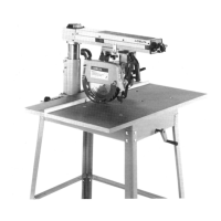
9. Place a straight edge (V) Fig. 24, on table mounting
brackets (N) as shown and adjust two center positions
(W) if necessary in the same manner on both brackets.
ASSEMBLING TABLE CLAMPS AND
TABLE CLAMP RODS
1. Unscrew the metal clamps from the table clamp rods
packed with the saw.
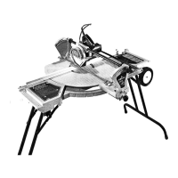
2. Position the metal clamp (A) Fig. 25, on the end of
table mounting bracket (B). NOTE: Assemble metal
clamp (A) so threaded hole (C) is on the inside of table
mounting bracket.
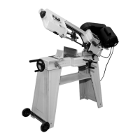
3. Insert threaded end of table clamp rod (D) Fig. 26,
through metal support (E) at the front of the saw and
thread rod through the tapped hole in table clamp (A) as
shown.
4. Assemble the remaining table clamp and table clamp
rod to the other side of the table in the same manner. Do
not tighten the table clamp rods at this time.
N
R
T
S
N
N
W
V
B
A
C
A
D
E
 Loading...