8
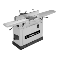
Fig. 2
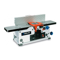
Fig. 3
A
B
C
D
B
E
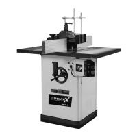
Fig. 4
ATTACHING EXTENSION WINGS TO
SHAPER TABLE
Attach the extension wing (A) Fig. 4 to shaper table (B)
using three 7/16-20 x 1" hex head screws (C) and flat
washers (D). Use a straight edge (E) Fig. 4 to level the
extension wing with the shaper table before tightening
the three screws (C). Attach and level the remaining
extension wing.
B
A
C
D
E
D
Fig. 5
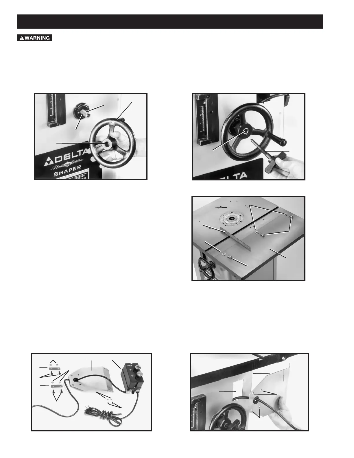
Fig. 6
1. The on/off switch (A) Fig. 5 and switch mounting bracket (B) are shipped inside the shaper cabinet. Open the side
door of the shaper cabinet, remove the switch package, and remove all packaging material.
2. Position the switch mounting bracket (B) Fig. 6 with the holes (C) over hole (D) in the shaper cabinet (E). Fasten
the bracket (B) to the cabinet (E) using the four 1/4-20 x 7/8" truss head screws (F) Fig. 5, 1/4-20 flange nuts (G)
and the two switch adapter plates (H).
G
F
H
G
H
F
B
A
L
K
B
D
E
C
C
ATTACHING SWITCH BRACKET AND ON/OFF SWITCH
For your own safety, do not connect the machine to the power source until the machine is
completely assembled, and you read and understand the entire instruction manual.
ATTACHING SPINDLE RAISING AND LOWERING HANDWHEEL
1. Insert key (A) Fig. 2 into slot in spindle raising and lowering shaft (B).
2. Place the handwheel (C) Fig. 2 on the spindle shaft (B). Fit the key (A) into the slot (D) in the handwheel. Insert the
set screw that holds the handwheel to the shaft. Tighten the screw firmly against the key.
3. Thread the lock knob (E) Fig. 3 into the spindle shaft (B).
ASSEMBLY
 Loading...