9
Fig. 9
Fig. 10
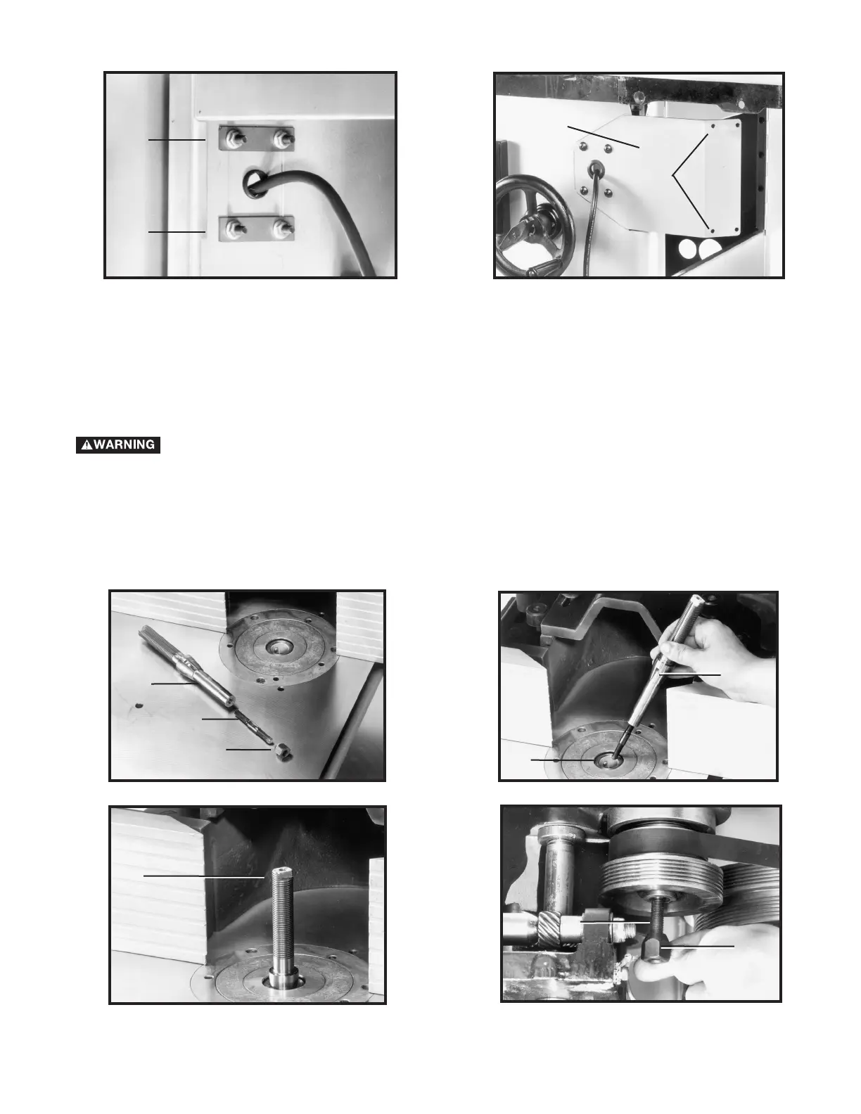
ATTACHING AND CHANGING SPINDLES
DISCONNECT TOOL FROM POWER SOURCE.
1. Thread one end of the tie rod (A) Fig. 9 into the threaded hole in the bottom of the spindle (B).
2. Insert tie rod and spindle into the spindle cartridge. Line up the pin (C) Fig. 10 with the notch (D) in the spindle.
3. Thread nut (E) Figs. 9 and 12 on the bottom end of the tie rod (A).
4. Use a wrench on the flats (F) Fig. 11 to hold the spindle while tightening the nut (E) Fig. 12 on the bottom of the
tie rod.
Fig. 11
Fig. 12
A
B
D
C
F
A
E
E
Fig. 8
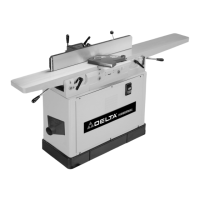
NOTE: Position the switch adapter plates (H) inside the shaper cabinet (Fig. 11).
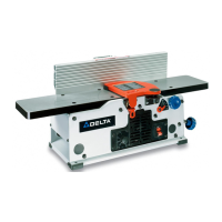
3. Attach the on/off switch (A) Fig. 5 to the switch mounting bracket (B) Fig. 8, through the two holes (J). Use two
#10-32 x 1/2" Phillips head screws (K) Fig. 5 and secure with #10-32 Keps nuts (L).
Fig. 7
H
H
B
J
 Loading...