Chapter 10 Function Cards
10-5
10.2.5 AS-F2DA
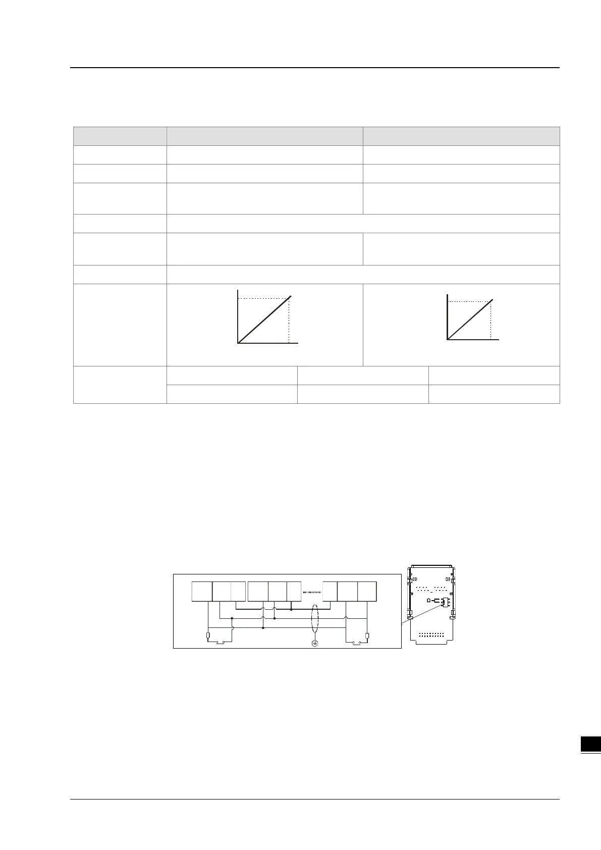
2 DC analog signal output channels:
Item Voltage Output Current Output
Analog Signal
0 V - 10 V 4 mA - 20 mA
Resolution
12-bit
12-bit
Digital Conversion
Limit
0 - 4000 0 - 4000
Error Rate
room temperature: ±0.5% ; full temperature range: ±1.0%
Impedance
Allowance
≥1 kΩ ≤500 Ω
Conversion Time*
1
2ms / CH
Characteristic
Curve
Di gital Value I nput
Voltage Output
10V
4000
0
Digital Value Input
Curr ent Output
20mA
4000
4
Digital Value
Output*
2
Card 1 SR172 (CH1) SR173 (CH2)
Card 2 SR174 (CH1) SR175 (CH2)
*1: The conversion time is the time for each channel to convert signals to hardware input signals. If you need to calculate
a complete conversion time, you need to add the PLC scan time.
*2: Use the MOV instruction to move the value to the SR to obtain the corresponding voltage output value.
10.2.6 AS-FCOPM
With its own standalone communication port, the AS-FCOPM card can work independently and can be either a slave or a
master node. After installing the extension card, use HWCONFIG in ISPSoft to configure the communication.
Wiring example
GND
CAN _H CAN _L
Master node
Slave node Slave node
Terminal
resistor
(120 ohm)
Shielded
cable
G ND
CAN _H C A N _L
GN D
C A N _H C AN_ L
Terminal
resistor
(120 ohm)
 Loading...