Chapter 8 ParametersASDA-A2R Series
Revision December, 2014
8-199
Command code
000Eh
Perform E-Cam alignement immediately and write the
correction value into the specified PR.
Macro parameters
P5-93 = DCBA:UZYX (8 digits, HEX)
YX (PR number) = 0~0x3F, it is invalid when the value
is set to 0.
UZ (Max. alignment correction rate) = 0~0x64 (%)
A (Trigger the specified PR directly) = 1: On, 0: Off
DCB = has to be set to 0
P5-94 (DI delay time compensation) = -25000 ~
+25000; Unit: usec.
P5-95 (available forward rate) = 0 ~ 100 (%)
P5-96 (target position of alignement X); Unit: pulse
number of master axis = 0 ~ (P5-84/P5-83) – 1.
Monitor variable 062(3Eh): It displays the current engaged position of
master axis (X)
This macro command can move the engaged position to the alignment
target position (X) when E-Cam is engaged. And write the alignment
correction value into the specified PR.
During E-Cam operation (When E-Cam is engaged), if desire to quickly
align the E-cam position to the mechanical referral point, sensor can be
used to trigger DI.EVx to execute this macro command.
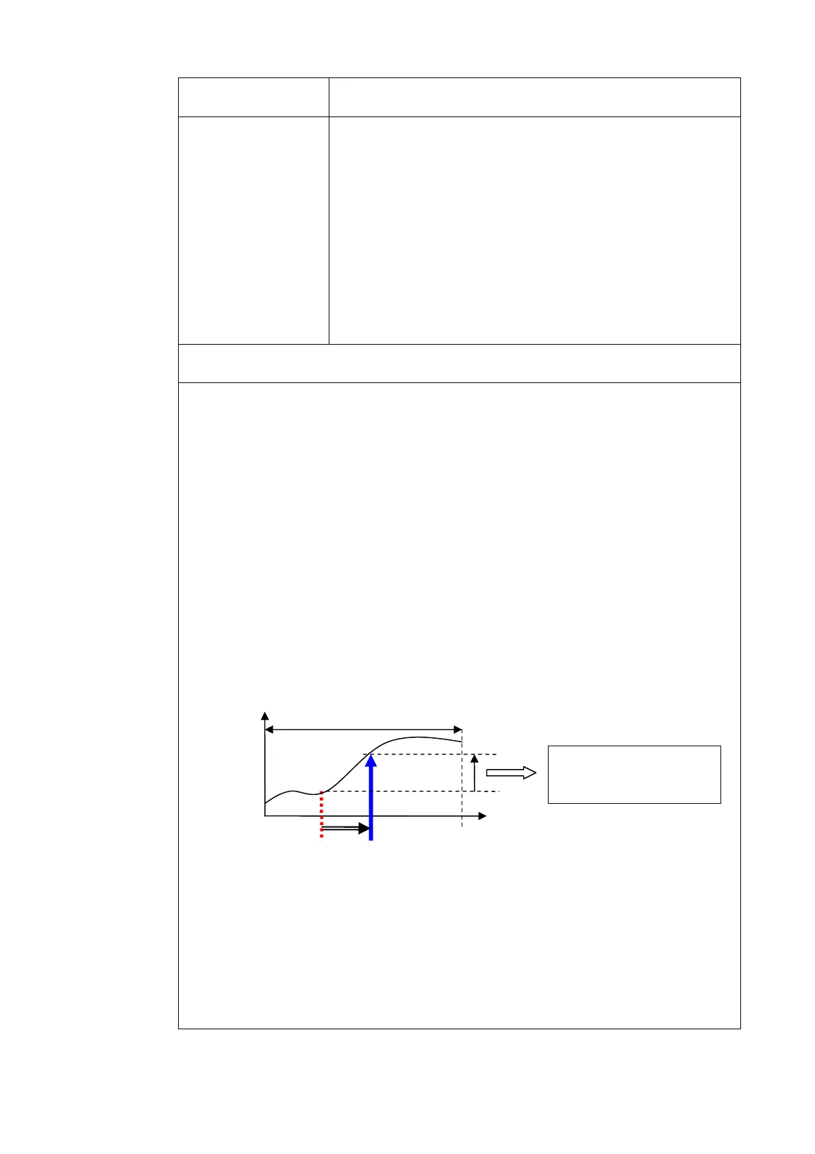
After E-Cam alignment is completed, the engaged position will move to the
new position. The excess or not enough moving distance after E-Cam
operates one cycle is called alignment correction value. It will be written into
PR specified by P5-93.YX. PR incremental command can be used to
compensate this value so that the slave axis position will remain and offset
the phase of E-Cam to align the referral position of machine. For some
applications, set value of P5-93.YX to 0 will do. Please note that PR can be
executed only when triggering the host controller.
*P5-93.UZ is able to limit the max. correction rate. The alignment target position
★ will be different from P5-96.
|alignment target position★ – current engaged position| / L <= P5-93.UZ %
*DI time delay compensation can be set via P5-94, it can correct the error caused
by different speed of motion.
Alignment target position
P5-96
Current engaged
position
Pulse number of master axis after rotating a cycle: (P5-84/P5-83) =
L
Master axis position (X)
Slave
axis
position
(Y)
lignment correction
value = Y_Diff

 Loading...