ASDA-M Chapter 3 Wiring
Revision December, 2014 3-19
can choose the desired DI/DO signal to meet the demand. Basically, the default setting of
DI/DO signal has already have the appropriate function which can satisfy the demand of
normal application.
Users have to select the operation mode based on the needs first (please refer to
Chapter 6.1 for the introduction of each mode) and refer to the following DI/DO table to
know the corresponding default setting of DI/DO signal and Pin No of the selected mode
in order to conduct the wiring.
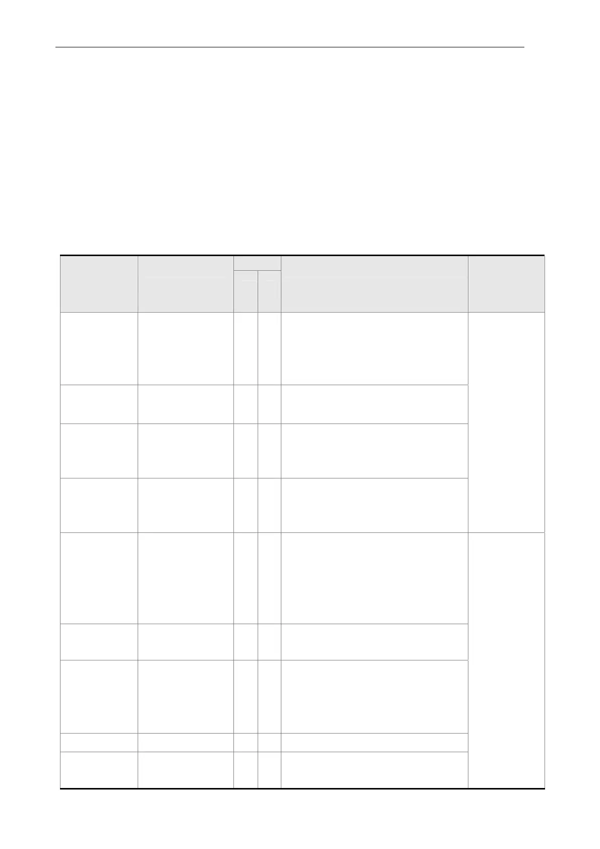
The table below lists the default setting of DI/DO signal function and pin No:
The explanation of DO signal default setting is as the followings.
DO Signal
Name
Operation Mode
Pin No
Function
Wiring
Method
(Refer to
3.3.3)
+ -
SRDY ALL 7 6
When the servo drive applies to the
power and no alarm (ALRM) occurs
in control circuit and motor power
circuit, this DO is ON.
C5/C6/
C7/C8
SON N/A - -
When the DI.SON is ON and the
motor servo circuit can operate
smoothly, this DO is ON.
ZSPD ALL 5 4
When the motor speed is slower than
the setting value of parameter P1-38,
this DO is ON.
TSPD
ALL (except PT,
PR)
- -
When the motor actual speed (r/min)
is faster than the setting value of
parameter P1-39, this DO is ON.
TPOS
PT, PR, PT-S,
PT-T, PR-S, PR-T
126
When the deviation between the
motor command and actual position
(PULSE) is smaller than the setting
value of parameter P1-54, this DO is
ON.
C5/C6/
C7/C8
TQL N/A - -
When torque is limiting, this DO is
ON.
ALRM ALL 28 27
When the alarm occurs (except
forward/reverse limit, emergency
stop, communication error, under
voltage), this DO is ON.
BRKR ALL - -
Control contact of mechanical brake
HOME ALL 3 2
When homing is completed, this DO
is ON.
 Loading...