CANopen Communication Module DVPCOPM-SL
Set up DVPCOPM-SL and IFD9503 according to the table below. For how to operate IFD9503, please refer to
Chapter 13.
Module Node address Baud rate (bps)
DVPCOPM-SL 01 1M
IFD9503 02 (connected to ASD-B) 1M
IFD9503 03 (connected to DVP-12SA) 1M
Set up ASD-B as follows:
Parameter Set value Explanation
P1-01 02 Control mode: speed mode
P1-09 100 (rpm) Internal speed command 1 (SP1)
P1-10 300 (rpm) Internal speed command 2 (SP2)
P1-11 500 (rpm) Internal speed command 3 (SP3)
P2-10 101 Function of DI1: Servo on
P2-11 114 Function of DI2: SPD0
P2-12 115 Function of DI3: SPD1
P2-18 102 Function of DO1: Output when servo on
P3-00 1 Modbus communication address
P3-01 5 (115,200 bps) Modbus baud rate
P3-02 1 (7,E,1) Modbus data format
P3-06 3F DI1 ~ DI6 controlled by communication
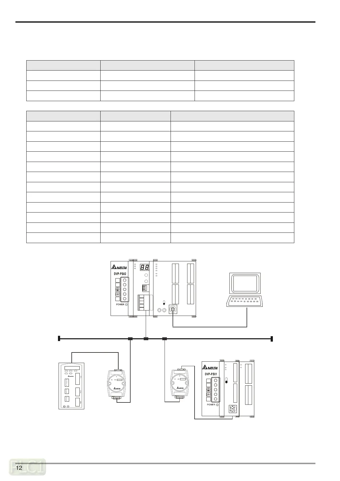
Constructing the CANopen network following the figure below.
PORT2PORT1
PORT2PORT1
CANopen
DVP28SV
DVPCOPM DVP28SV
RUN
STOP
D
V
P
-
1
2
S
A
D
V
P
-
0
8
S
T
L
N
0V
L
N
0V
DVP-PS02
DVP-08STDVP-12SA
IFD9503
DVPCOPM-SL
RS-232
CANopen
network configuration tool
Node 1
Node 2
Node 3
ASD-B
About the connection between IFD9503 and PLC, IFD9503 and ASD-B, or IFD9503 and other equipment, please refer
to Chapter 13. For the electrical specifications of ASD-B, please refer to ASD-B user manual.
DVP-PLC Operation Manual
12
 Loading...