Chapter 5 Main Circuit TerminalsMS300 (IP66 / NEMA 4X)
5-3
Terminals for connecting DC reactor, external brake resistor and DC
circuit
Terminals for connecting the DC reactor, as shown in Figure 5-2 below, are
to improve the power factor and harmonics. At delivery they are shorted by
a jumper. Remove the jumper before connecting the DC reactor.
You must tightly fasten the jumper when it does not connect the DC reactor,
use DC+/+1, +2/B1 to execute common DC BUS, or connect with a brake
resistor; otherwise the drive might lose power or break the terminals. Refer
to Figure 5-2.
DC reactor optional ( )
D
+/ +
+
/B
Connect a brake resistor in applications with frequent deceleration, short
deceleration time, too low braking torque, or increased braking torque.
B
ake
esis
o
(optional)
+
/B
B
Connect the external brake resistor to the terminals [+2/B1], [B2] on AC
motor drives.
DO NOT short-circuit or connect a brake resistor directly to DC+/+1 and
DC-, +2/B1 to DC-; otherwise the drive will be damaged.
Connect DC+ and DC- in common DC BUS applications. Refer to Section
5-1 (Main Circuit Terminal) for the wiring terminal specification and the wire
gauge information.
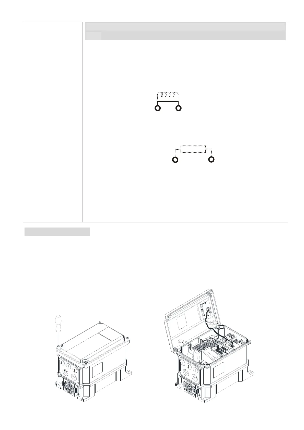
Open the front cover
Open the front cover before connecting the main circuit terminals and control circuit terminals. Open
the cover according to the Figure 5-4 and Figure 5-5 below.
The figure below shows the Frame B model for example. Opening the cover on the other frame sizes
is similar.
Loosen the four screws on the front
cover with a Phillips head screwdriver.
Open the front cover to the left.
Figure 5-4
Figure 5-5
Torque:
4–6 kg-cm /
[3.5–5.2 lb-in.] /
[0.39–0.59 Nm]
Figure 5-3
Figure 5-2

 Loading...


