Chapter 6 Control Circuit Terminals MS300 (IP66 / NEMA 4X)
6-5
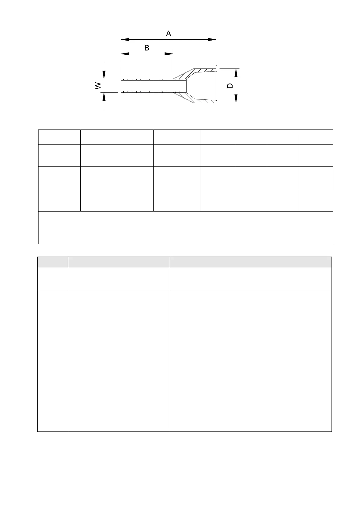
Figure 6-8
ecommended models or dimensions for ferrule terminals Unit: mm
Wire Gauge Manufacturer Model Name A (MAX) B (MAX) D (MAX) W (MAX)
0.25 mm
2
[24 AWG]
PHOENIX CONTACT AI 0,25- 8 YE 12.5 8 2.6 1.1
0.34 mm
2
[22 AWG]
PHOENIX CONTACT AI 0,34- 8 TQ 12.5 8 3.3 1.3
0.5 mm
2
[20 AWG]
PHOENIX CONTACT AI 0,5 - 8 WH 14 8 3.5 1.4
Recommended specifications and models for ferrules:
CRIMPFOX 10S - 1212045, Manufacturer: PHOENIX CONTACT
DNT13-0101, Manufacturer: DINKLE
Table 6-2
Terminals Terminal Function Default (NPN mode)
+24 V
Digital control signal common
(Source)
+24 V±10 % 100 mA
MI1
–
MI7
Multi-function input 1–7
Refer to Pr.02-01–02-07 to program the multi-function
inputs MI1–MI7.
Source Mode
ON: the activation current is 3.3 mA ≥ 11 V
DC
OFF: cut-off voltage ≤ 5 V
DC
Sink Mode
ON: the activation current is 3.3 mA ≤ 13 V
DC
OFF: cut-off voltage ≥ 19 V
DC
When Pr.02-00 = 0, MI1 and MI2 can be
programmed.
When Pr.02-00 ≠ 0, the function of MI1 and MI2 is
according to Pr.02-00 setting.
When Pr.02-07 = 0, MI7 is pulse input with
maximum frequency 33 kHz (See Pr.10-00,
Pr.10-02, Pr.10-16).

 Loading...


