Chapter 6 Control Circuit Terminals MS300 (IP66 / NEMA 4X)
6-7
Terminals Terminal Function Default (NPN mode)
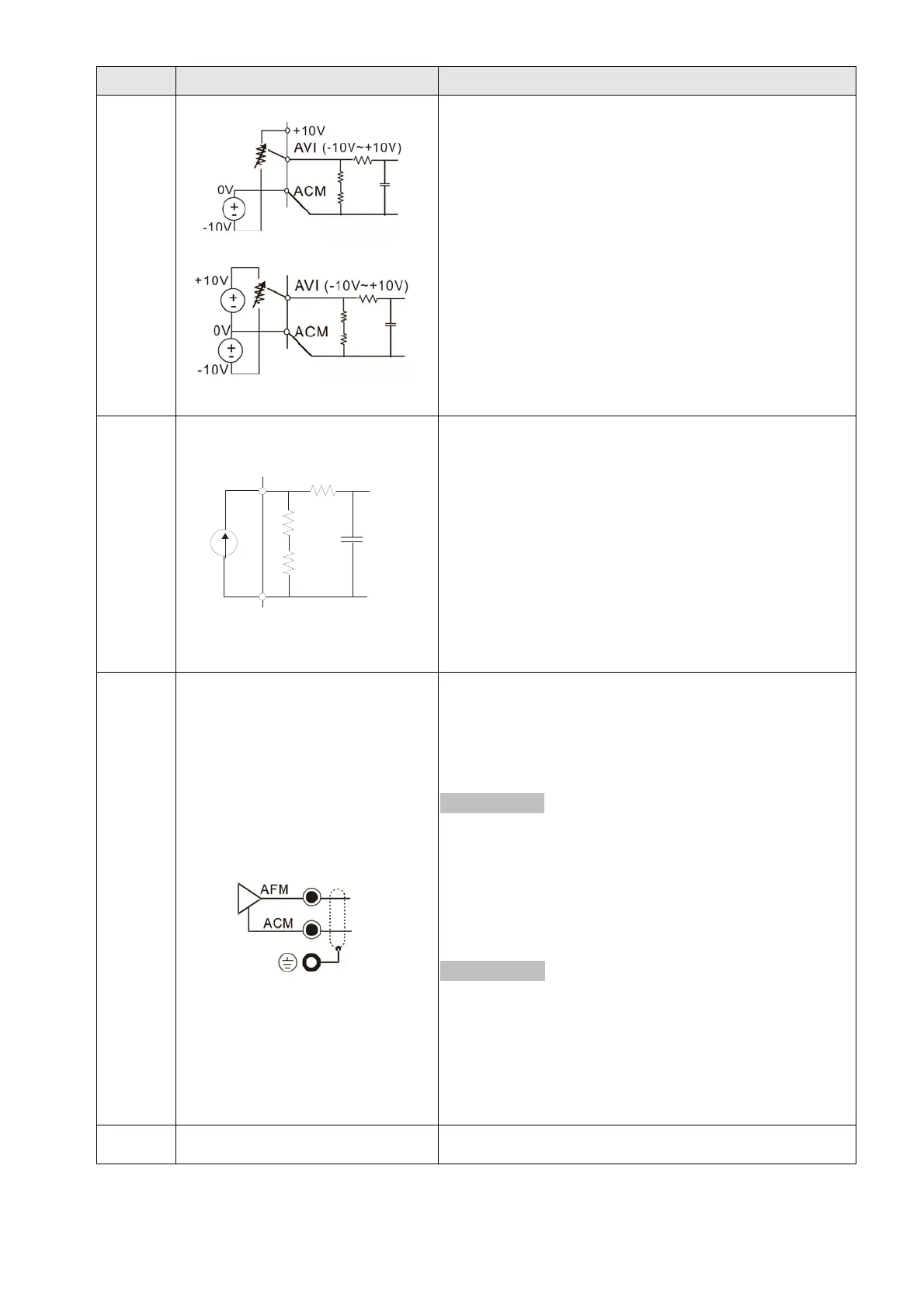
AVI
Analog voltage input
internal circuit
Figure 6-11
internal circuit
Figure 6-12
Impedance: 20 kΩ
Range 0–Maximum Output Frequency (Pr.01-00):
0–10 V / -10–10 V
Range switching by Pr.03-00, Pr.03-28.
AVI resolution = 10 bits
ACI
Analog current input
CM
C
ACI circuit
internal circuit
Figure 6-13
Impedance: Current mode is 250 Ω; voltage mode is
20 kΩ.
Range 0–Maximum Output Frequency (Pr.01-00):
0–20 mA / 4–20 mA / 0–10 V
Range switching by Pr.03-01, Pr.03-29.
ACI resolution = 12 bits
AFM
Multi-function analog voltage
output
Figure 6-14
Switch: the AFM default is 0–10 V (voltage mode). Use
the switch and Pr.03-31 to change to current mode
(0–20 mA / 4–20 mA). You must follow the indication
on the back side of the front cover or page 6-1 of the
user manual when using the switch.
Voltage mode
Range: 0–10 V (Pr.03-31=0) corresponding to the
maximum operating range of the control
object
Maximum output current : 2 mA
Maximum Load: 5 kΩ
Current mode
Range: 0–20 mA (Pr.03-31=1) / 4–20 mA (Pr.03-31=2)
corresponding to the maximum. operating
range of the control object
Maximum load: 500 Ω
AFM resolution = 10 bits
ACM Analog Signal Common Common for analog terminals

 Loading...


