DVP-ES3 Series Operation Manual
5-20
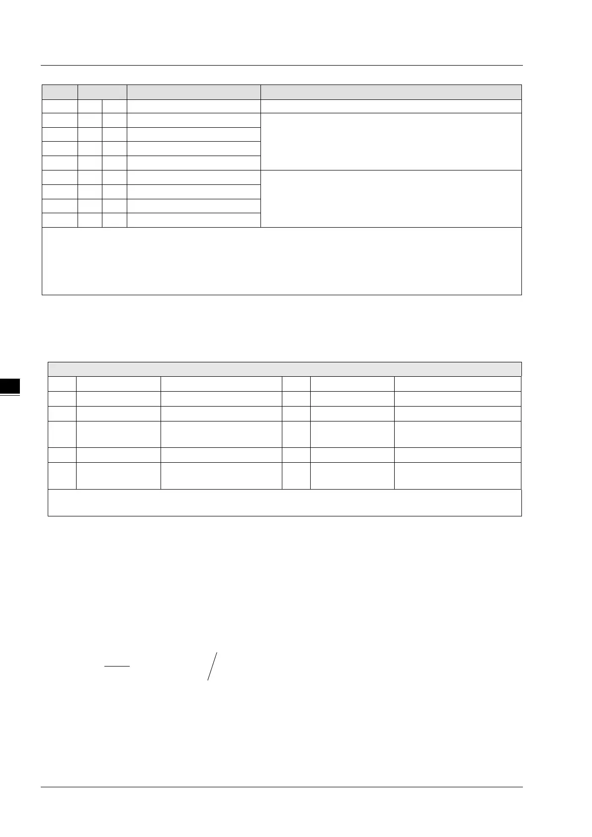
to CH1~CH4 for upper bound detection result.
Set value of CH1 upper bound
Set value of CH1~CH4 upper bound. Default = K32000.
Set value of CH2 upper bound
Set value of CH3 upper bound
Set value of CH4 upper bound
Set value of CH1 lower bound
Set value of CH1~CH4 lower bound. Default = K-32000.
Set value of CH2 lower bound
Set value of CH3 lower bound
Set value of CH4 lower bound
Symbols:
O: When CR#41 is set to H’5678, the set value of CR will be saved.
X: Set value will not be saved.
R: You can use FROM instruction to read data.
W: You can use TO instruction to write data.
※ CR#0 for module reset
You can use CR#0 to reset all the settings by simply writing H’4352 in CR#0 and wait for one second before turning the
power OFF and then ON again, all the modules connected will be initialized. It is suggested to connect to only one module
for module reset. And this is only available for firmware V1.10 or later.
※ CR#43: Error status value. See the table below:
bit3 K8 (H’8) CH1 Conversion error bit11 K2048 (H’0800)
Upper / lower bound setting
Set value changing prohibited
bit5 K32 (H’20) CH3 Conversion error bit13 K8192 (H’2000)
Communication breakdown on
next module
Note: Each error status is determined by the corresponding bit (b0 ~ b13) and there may be more than 2 errors
occurring at the same time. 0 = normal; 1 = error
Adjust A/D Conversion Curve
You can adjust the conversion curves according to the actual needs by changing the Offset value (CR#28 ~ CR#31) and
Gain value (CR#34 ~ CR#37).
Offset: The corresponding voltage/current input value when the digital output value = 0.
Gain: The corresponding voltage/current input value when the digital output value = 16,000.
Equation for voltage input Mode0 / Mode2:
( )
OffsetGainOffset
V
VX
Y −
−××= 32000
10
16000
)(
)(
Y=Digital output, X=Voltage input
Resolution: 0.3125mV = 20V/64,000 = 10V/32,000

 Loading...


