Chapter 2 Specifications and System Configuration
2-20
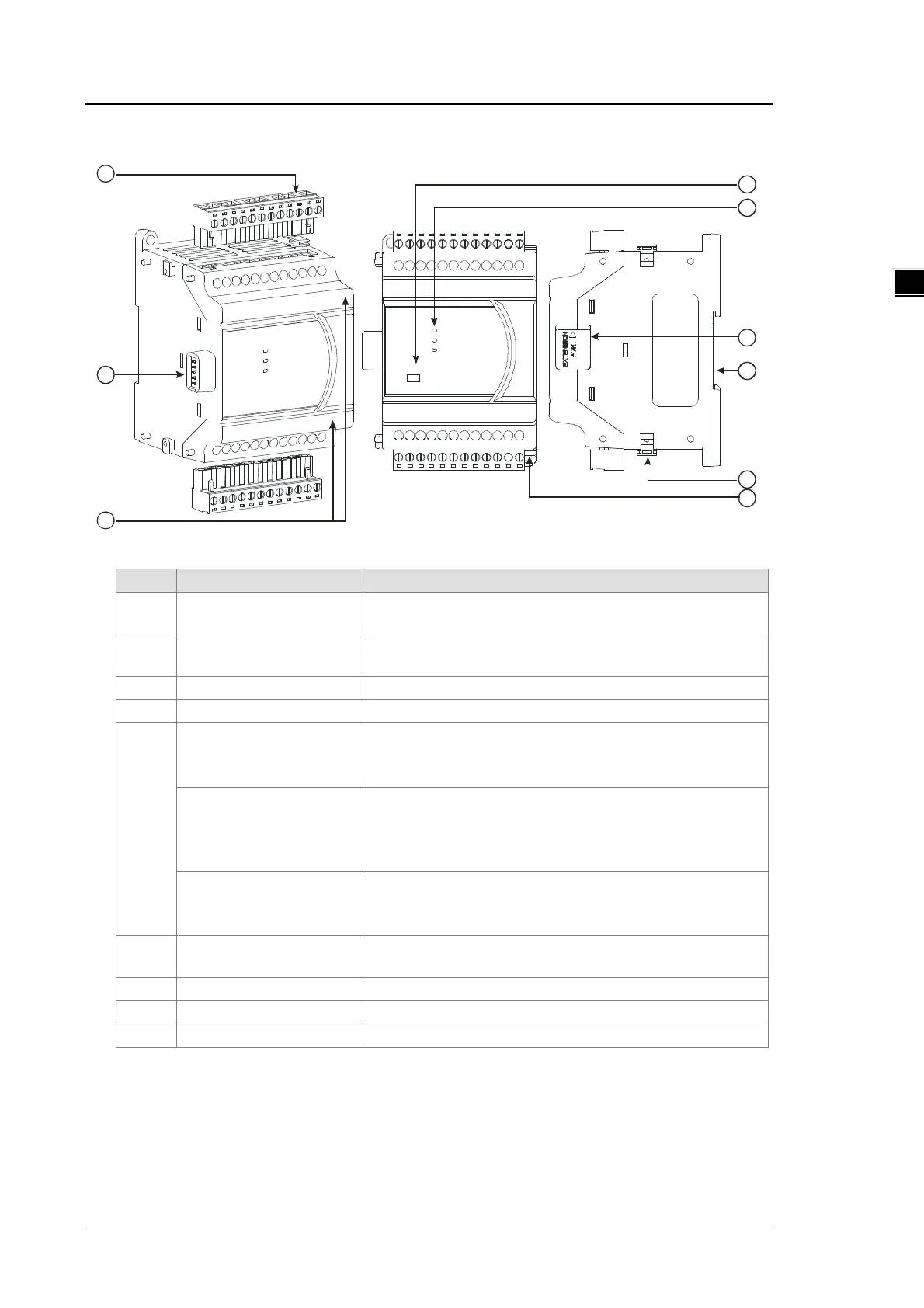
2.4.2 Analog Input/Output Module Profiles
Unit: mm
1 Removable terminal block
The inputs are connected to sensors.
The outputs are connected to loads to be driven.
2
External module connection
port
Connects the modules
5
POWER LED indicator
Indicates the status of the power supply
ON: the power is on
ERROR LED indicator
Error status of the module
ON: a serious error occurs in the module.
OFF: the module is normal.
Blinking: a minor error occurs in the module.
Analog to digital conversion
indicator
Indicates the analog to digital conversion status
Blinking: conversion is taking place
6
External module connection
port
Connects the modules
7 DIN rail slot (35 mm) For the DIN rail
8 I/O module securing clip
Secures the modules
Secures the module on the set

 Loading...


