Chapter 2 Specifications and System Configuration
2-12
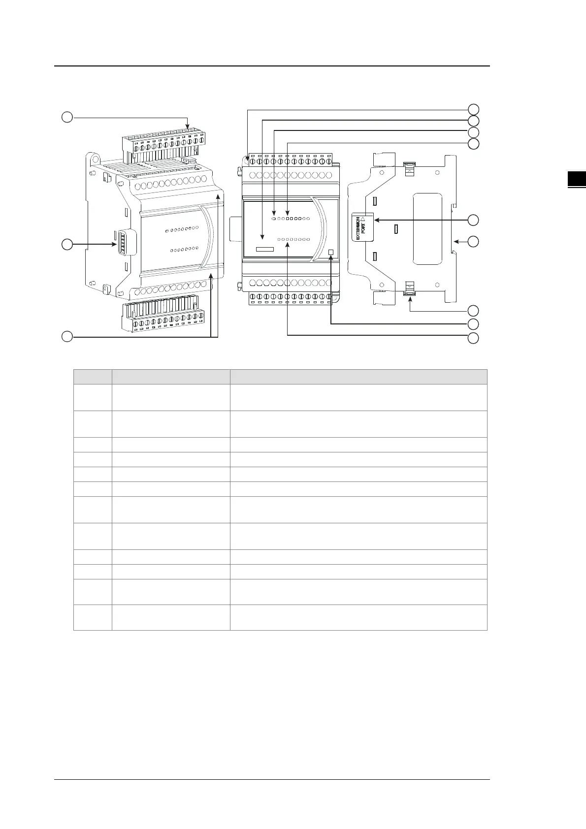
2.3.2 Digital Input/Output Module Profiles
1 6XP 2
8DI / 8 DO
R
1
4
5
3
6
7
8
2
9
10
11
12
Unit: mm
1 Removable terminal block
The inputs are connected to sensors.
The outputs are connected to loads to be driven.
2
External module connection
port
Connects the modules
Secures the module on the set
5 Model name Model name of the module
Indicates the power status of the CPU module
7 Input/output LED indicator
If there is an input signal, the input LED indicator is ON.
If there is an output signal, the output LED indicator is ON.
8
External modul
Connects the modules
10 I/O module securing clip Secures the modules
11 Output type
R: Relay output
12 Input/Output LED
If there is an input signal, the input LED indicator is ON.
If there is an output signal, the output LED indicator is ON.

 Loading...


