Ethernet Communication Module DVPEN01-SL
DVP-PLC Operation Manual
8
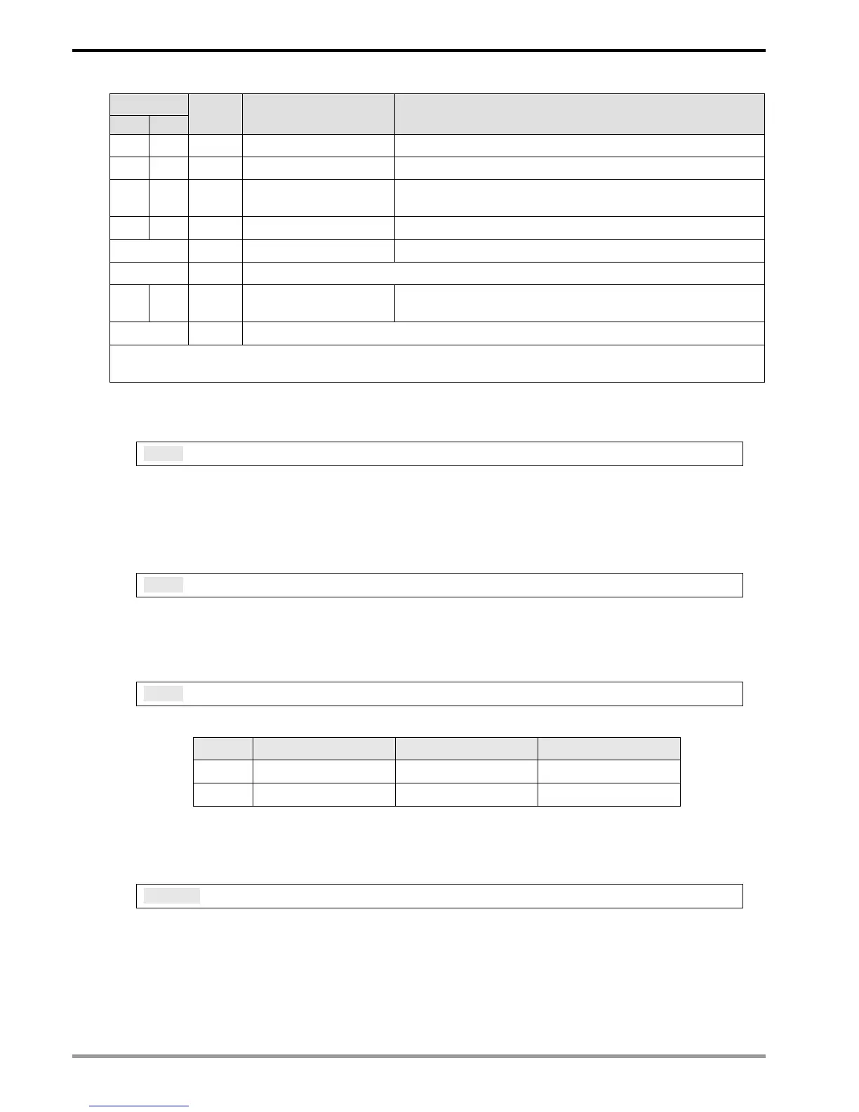
CR#
HW LW
Attribute Content Explanation
#115 R/W Modbus TCP trigger Setting up whether to send out data in Modbus TCP mode
#116 R/W Modbus TCP status Displaying current status of Modbus TCP mode
#118 #117 R/W
Modbus TCP
destination IP
Setting up destination IP address for Modbus TCP transaction
#119 R/W Modbus TCP data length Setting up the data length for Modbus TCP transaction
#219 ~ #120 R/W Modbus TCP data buffer Data buffer of Modbus TCP for storing sending/receiving data
#248 ~ #220 - Reserved
#251 R Error code
Displaying the errors. See table of error codes in the following
section for more information.
#255 ~ #252 - Reserved
Symbols “R” refers to “able to read data by FROM instrcution”; “W” refers to “able to write data by TO
instrcution”.
4.2 Explanations on CR
CR#0: Model Name
Explanations:
1. Model code of DVPEN01-SL = H’4050.
2. You can read the model code in the program to see if the I/O module exists.
CR#1: Firmware Version
Explanations:
The firmware version of DVPEN01-SL is displayed in hex, e.g. H’0100 indicates version V1.00.
CR#2: Communication Mode
Explanations:
Bit No. Mode “0” “1”
b0 Modbus TCP Disable Enable
b1 Data exchange Disable Enable
E-mail Functions
CR#3 ~ 6: E-Mail Event 1 ~ 4 Trigger
Explanations:
When the CR is set as “1”, E-mail sending will be enabled. After the sending is completed, the
CR will automatically be reset as “0”. Note: Please trigger by differential instructions.