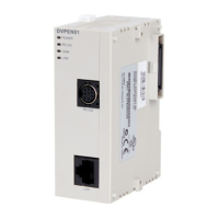
Ethernet Communication Module DVPEN01-SL
DVP-PLC Operation Manual
5
2.3 LED Indicators
Indicator Color Indication
POWER Green Power indication
RS-232 Red Communication status of the series port
100M Orange Network connection status
LINK Green Network communication speed
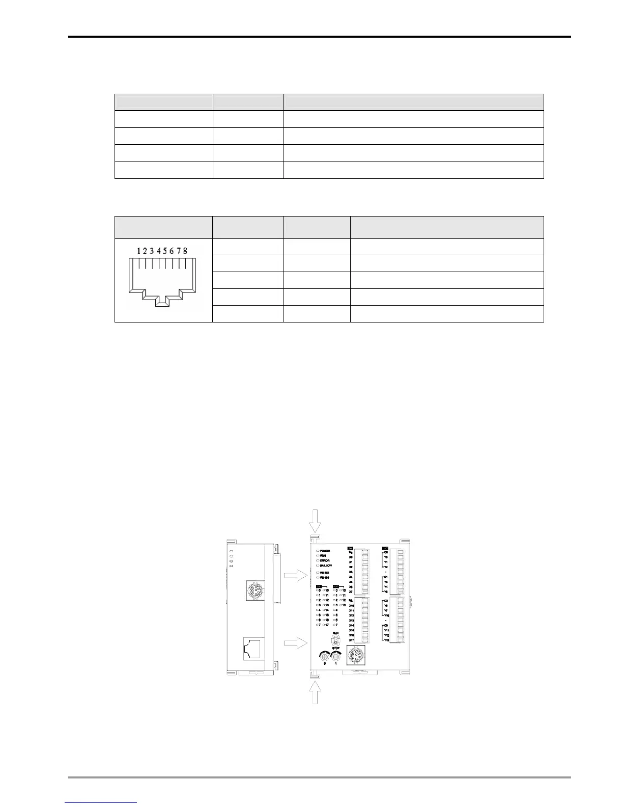
2.4 RJ-45 PIN Definition
RJ-45 sketch Terminal No. Definition Explanation
1 Tx+ Positive pole for data transmission
2 Tx- Negative pole for data transmission
3 Rx+ Positive pole for data receiving
6 Rx- Negative pole for data receiving
4, 5, 7, 8 - N/C
3 Installation & Wiring
This section gives instructions on how to connect DVPEN01-SL with PLC MPU and how to connect
DVPEN01-SL to the network.
3.1 Installation
Connect PLC MPU to DVPEN01-SL
z Adjust the I/O module clip on the left side of the MPU.
z Meet the I/O module port of the MPU with DVPEN01-SL as shown in the figure below.
z Fasten the I/O module clip on the left side of the MPU.
DVP28SV
LAN
RS-232
RS-232
LINK
100M
DVPEN01
POWER
Connect DVPEN01-SL to other I/O modules
z To connect DVPEN01-SL with the other I/O module, lift the extension clip of the I/O module by a
screwdriver and open the side cover.