Ethernet Communication Module DVPEN01-SL
DVP-PLC Operation Manual
13
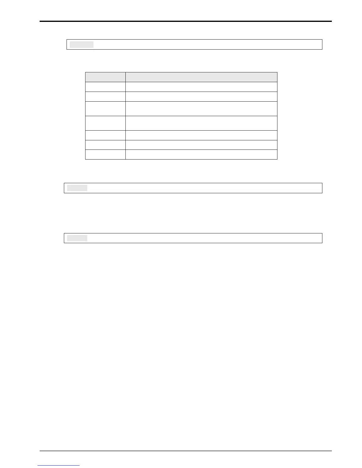
CR#251: Error Code
Explanations:
Table of error code:
Bit No. Error
b0 The network is not yet connected.
b1 Incorrect IP setting
b2
CR#13 is set as “transmitting data”, but the data exchange
is forbidden.
b3
CR#13 is set as “transmitting data”, but the data exchange
mode has not yet been enabled.
b4 NTP-Server connection fails.
b7 SMTP-Server connection fails.
b8 DHCP has not obtained the correct network parameter.
RTU Mapping
CR#15: Enabling Flag for RTU Mapping
Explanations:
1: Enable; 0: Disable. Default = 0
Firmware V2.0 and later versions support RTU mapping.
CR#16: Connection Status of RTU Mapping Slave
Explanations:
b3 ~ b0 display the connection status of RTU slave. The connection may encounter some
problems when any of the bits becomes 0. Firmware V2.0 and later versions support RTU
mapping.
b0: Status of RTU slave 1
b1: Status of RTU slave 2
b2: Status of RTU slave 3
b3: Status of RTU slave 4
4.3 Numbering of Left-Side Modules
After DVPEN01-SL is installed properly, you need to compile the PLC program to control the special I/O
module. PLC offers FROM instruction (for reading) and TO instruction (for writing) to control the control registers
(CR) in the special I/O module.
Numbering of the modules: Every special I/O module connected to PLC MPU has a No. to allow you to know
which module is which when compiling the PLC program. The first special I/O module attached at the left hand
side of the PLC MPU is numbered as K100, the second as K101, the third K102, and so on.