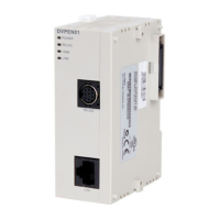
Ethernet Communication Module DVPEN01-SL
DVP-PLC Operation Manual
10
CR value Status
0 Data have not yet been received.
1 Data exchange is in progress.
2 Data exchange is successful.
3 Data exchange fails.
CR#25, 26: Destination IP
Explanations:
To set up the Slave IP address for data exchange manually, write “0” into CR#28 first before
setting up the destination IP. For example, if the user wants to set the destination IP address to
192.168.0.2, write H’0002 to CR#25 and H’C0A8 to CR#26. (K192 = H’C0, K168 = H’A8, K0 =
H’00, K2 = H’02).
CR#28: Destination Slave ID
Explanations:
When you set up the Salve ID (i.e. K1 ~ K255) for data exchange, DVPEN01-SL will
automatically search for the corresponding IP address from the Slave IP list. For example, if the
ID is set as “0”, the value in CR#25 and #26 will be regarded as the destination IP.
CR#29 ~ 48: Data Transmission Buffer
Explanations:
Storing the data to be transmitted to the remote MPU.
CR#49 ~ 68: Data Receiving Buffer
Explanations:
Storing the data received from the remote MPU.
CR#81: Read Address for Data Exchange
Explanations:
Setting up manually the Modbus address of the register for Slave data exchange. Only register
address is allowed (e.g. D0 = H’1000).
CR#82: Read Length for Data Exchange
Explanations:
The number of receiving registers (K1 ~ K100) in data exchange.

 Loading...