Ethernet Communication Module DVPEN01-SL
DVP-PLC Operation Manual
51
END
M1013
K100 K1
K100
K100 K1
M2 M1
M1SET
M1
TOP K28
TOP
TOP
K100TOP
SET M2
M1RST
K100 K1
M2
K14 D14
RST
M2
RST M2
= D14 K2
= D14 K3
FROM
K1
K100 K1TOP
K100TOP K1 K1
K0
K0
K26
K25
K29
K14
K13
D100 K7
H4
HC0A8
D100TDR
M1000
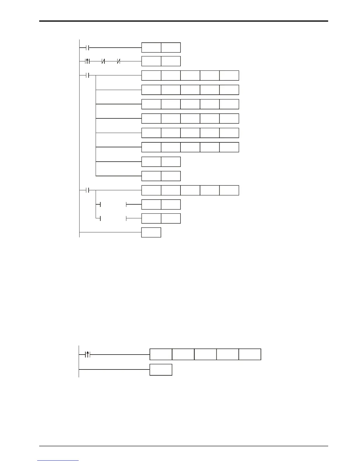
Explanations:
• The data exchange will be executed every one second.
• Write “0” into CR#28, and PLC_B will use CR#25 ~ CR#26 as the IP address of the destination
PLC.
• Write the IP address of PLC_A into CR#25 and CR#26. The first two IP codes (192.168 =
H’C0A8) should be written into CR#26, and the last two IP codes (0.4 = H’0004) into CR#25.
• Write the data in RTC into CR#29 ~ CR#35.
• Write “1” into CR#13 to start the data exchange.
• CR#14 = 2 refers to successful execution. CR#14 = 3 refers to failed execution.
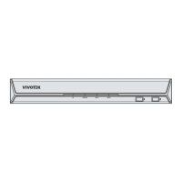
2. Compile the ladder diagram for PLC_A and download it to PLC_A.
END
M1013
K7D0K49K100FROM
Explanations:
• The received data are stored in CR#49 ~ CR#55.
• The data received every one second are written into D0 ~ D6.