ASDA-A2 Chapter 12 Absolute System
12-10 Revision February, 2017
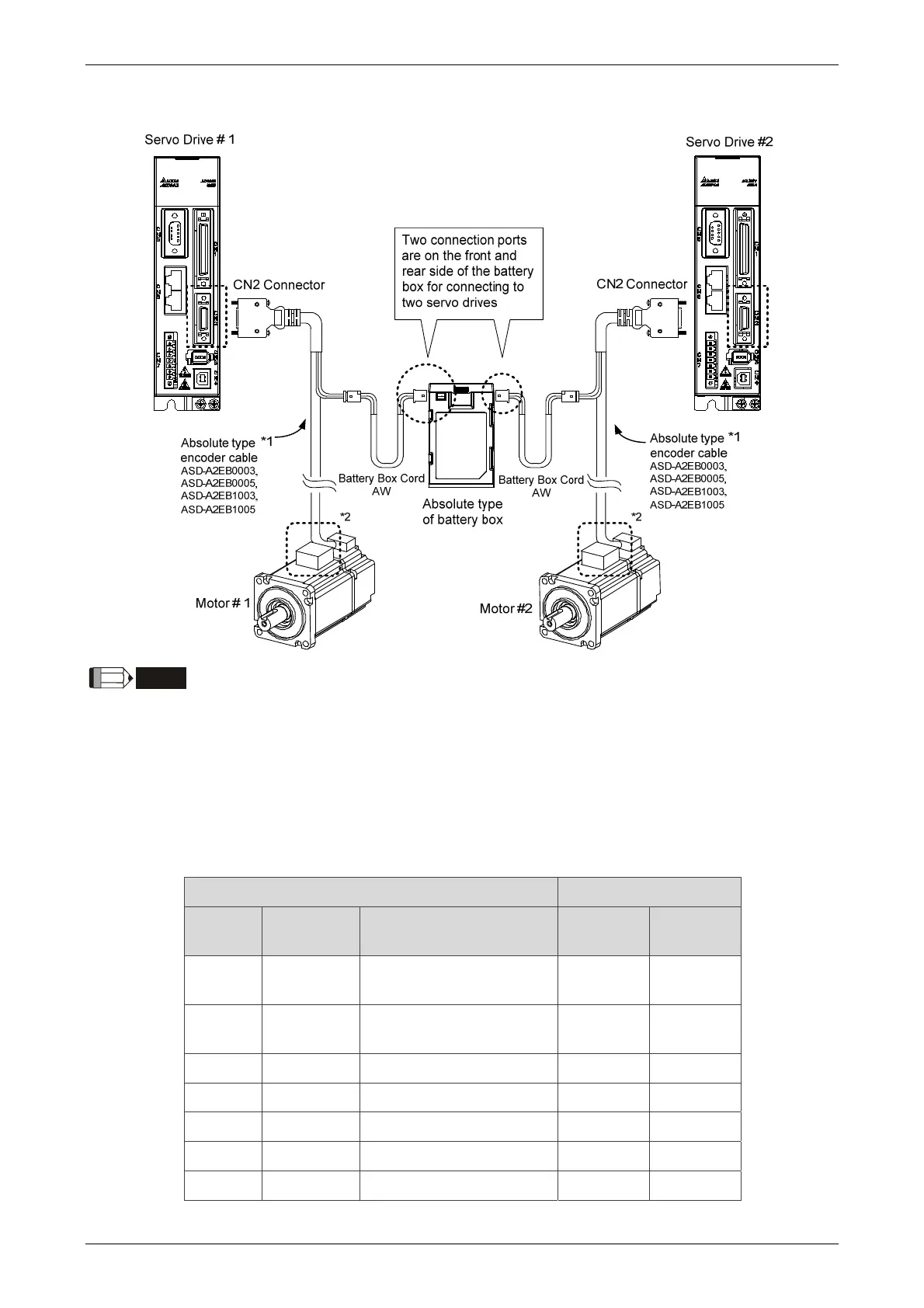
Dual Battery Box (Connect to CN2)
NOTE
This is the wiring diagram for connecting to a single battery box. The scale of the objects does not
match the dimensions as shown in the drawing above. For different models of AC servo drives and
motors, the connection cables may differ.
1* and 2* Please refer to section 12.1.3.
3* Definition of CN2 connector
Please conduct the wiring according to the following instructions. Wrong wiring might
cause battery explosion.
CN2 Connector Motor Connector
Pin No
Terminal
Symbol
Function and Description
Military
Connector
Quick
Connector
5 T+
Serial communication
signal input/output (+)
A 1
4 T-
Serial communication
signal input/output (-)
B 4
7 BAT+ Battery 3.6V C 2
9 BAT- Battery ground D 5
14, 16 +5V Power+5V S 7
13, 15 GND Power ground R 8
- Shield Shield L 9
 Loading...


