ASDA-A2 Chapter 8 Parameters
Revision February, 2017 8-151
P4-07■
ITST Multi-function of Digital Input
Address: 040EH
040FH
Operational
Interface:
Panel / Software Communication
Related Section:
Section 4.4.4
Table 9.2
Default:
0
Control
Mode:
ALL
Unit:
-
Range:
0 ~ 0x3FFF
Data Size:
16-bit
Format:
Hexadecimal
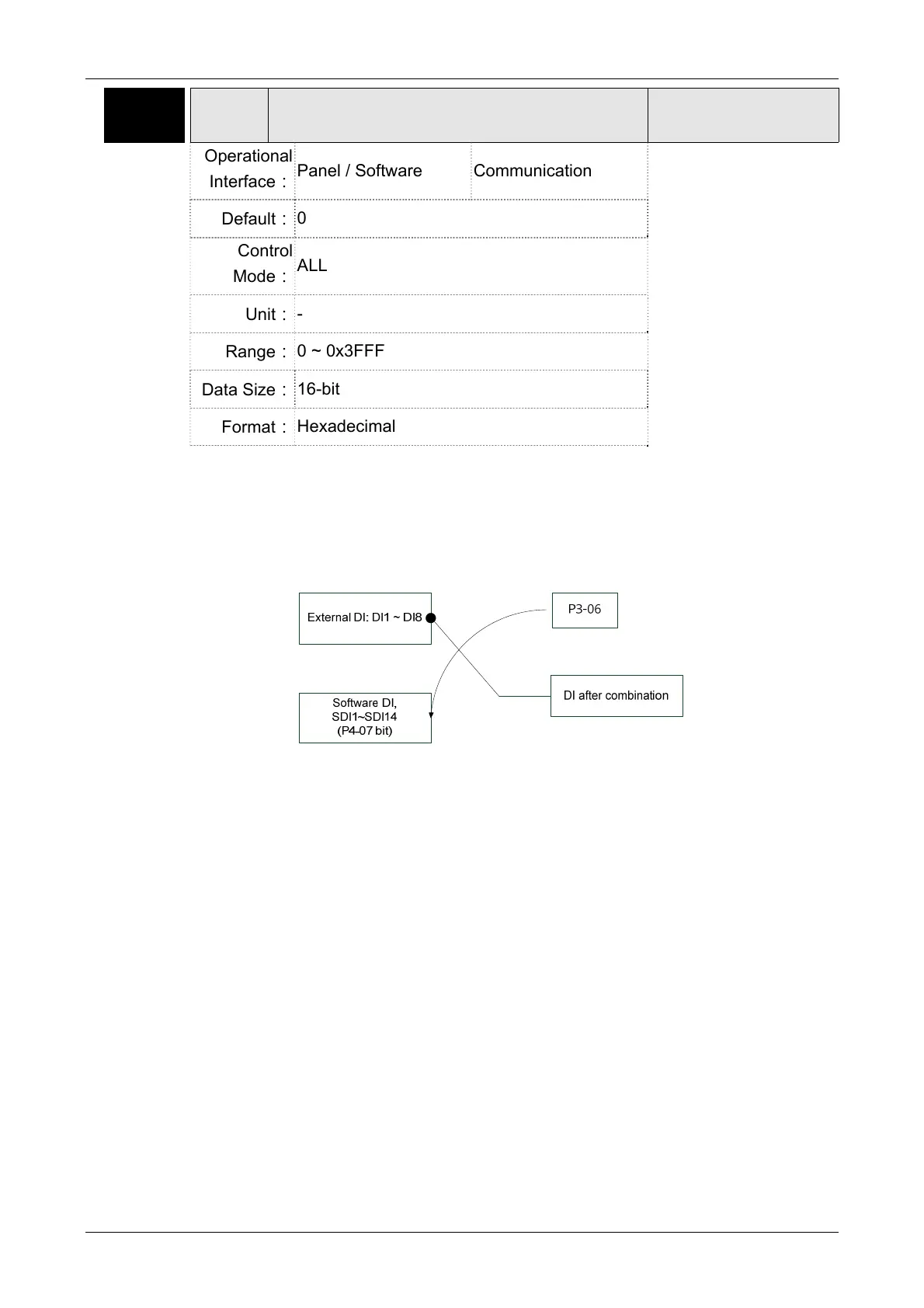
Settings:
The DI input signal can come from external terminal (DI1 ~ DI8; EDI9 ~
EDI14) or software SDI1 ~ 14 (Bit 0 ~ 13 of corresponding parameter
P4-07) and is determined by P3-06. The corresponding bit of P3-06 is
1, which means the source is software SDI (P4-07). If the
corresponding bit is 0, then the source is hardware DI. See the
following graph:
Read parameters: shows the DI status after combination
Write parameters: writes the software SDI status
For example:
The value of reading P4-07 is 0x0011, which means DI1 and DI5 is ON
after combination.
The value of writing P4-07 is 0x0011, which means software SDI1 and
SDI5 is ON.
Please refer to P2-10 ~ P2-17 for the function program of digital input
pin DI (DI1~DI8) and P2-36 ~ P2-41 for extended DI (EDI9 ~ EDI14).
 Loading...


