Chapter 7 Option Cards | VFD-ED
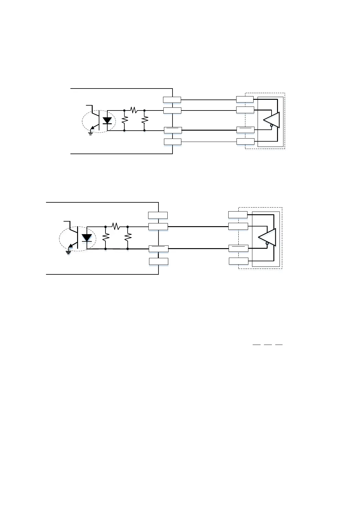
4. Line driver output encoder application: Each set of input current is 5–15 mA. If input voltage
uses 5V or 12V external power, connect the encoder power externally. See the PG wiring
Figure 7-17 below.
EMED-PGABD-x Line Driver Encoder
Figure 7-16
EMED-PGABD-x Line Driver Encoder
Figure 7-17
NOTE:
Verify that the SW1 is set to the correct output voltage before powering ON.
Keep the motor drive wiring away from any high voltage lines to avoid interference.
When using push-pull output and voltage output, short-circuit A , B , Z to 0V.
When using open collector output, short-circuit A, B, Z to V P.
4.7kohm
VP
0V
ABZ/UVW
ABZ/UVW
VCC
ABZ/UVW
ABZ/UVW
GND
4.7kohm
VP
0V
ABZ/UVW
ABZ/UVW
VCC
ABZ/UVW
ABZ/UVW
GND
External
power
(5V or 12V)

 Loading...


