12 Descriptions of Parameter Settings | VFD-ED
03 Analog Input / Output Parameters
: You can set this parameter during operation
Analog Input 1 (AUI1)
Default:1
Reserved
Analog Input 2 (AUI2)
Default: 0
Settings Control Mode
VF VFPG SVC FOCPG
FOCPM
0: No function
1: Frequency command (speed limit under torque
control mode)
2: Torque command (torque limit under speed
mode)
3: Load compensation
4–5: Reserved
6: P.T.C. thermistor input value
7: Positive torque limit
8: Negative torque limit
9: Regenerative torque limit
10: Positive/negative torque limit
When using the Frequency command or speed limit under torque control mode, the corresponding value
for 0 to ±10 V or 4–20 mA is 0–maximum output frequency (Pr.01-00).
When using the Torque command or torque limit, the corresponding value for 0 to ±10 V or 4–20 mA is 0–
maximum output torque (Pr.07-14).
When using torque compensation, the corresponding value for 0 to ±10 V or 4–20 mA is 0–moto’s rated
torque.
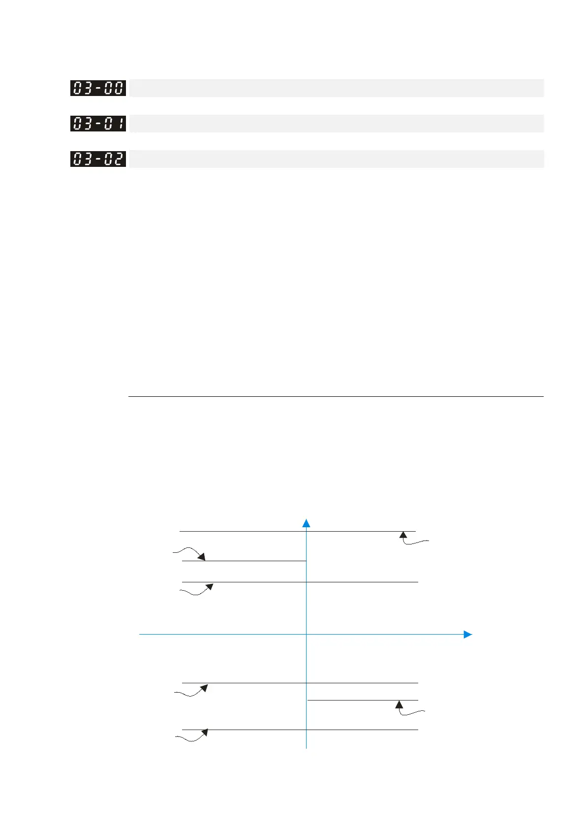
Positive to rque
Reverse
03-00~0 2=7
Positive torque limit
03-00~0 2=8
Neg ative to rque limit
03-00~0 2=9
Reg enerative
torque limit
03-00~0 2=10
Positive/negat ive torque limit
Neg ative Torq ue
F orw ard
03-00~0 2=10
Positive/negat ive torque limit
03-00~0 2=9
Reg enerative
torque limit

 Loading...


