12 Descriptions of Parameter Settings | VFD-ED
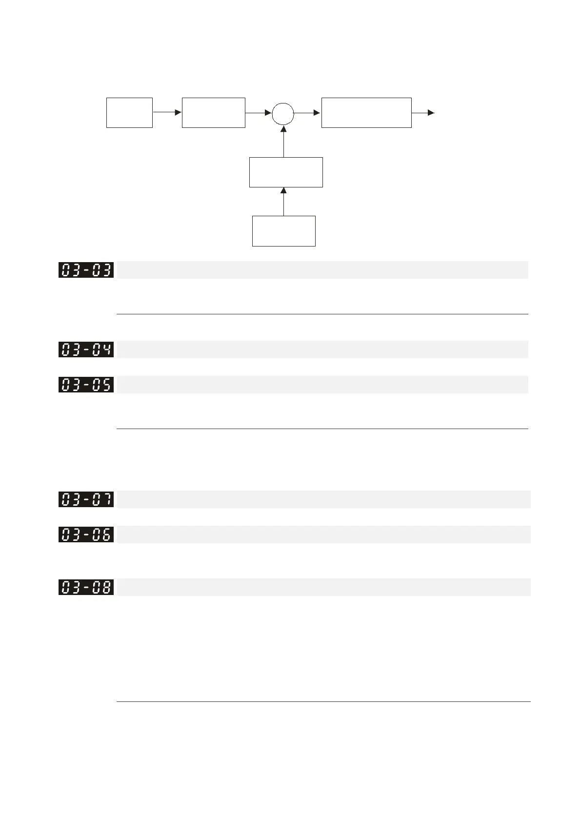
07-19: Source of torque offset
03-00~02: Analog input selections (AUI1/ACI/AUI2)
03-03~05: Analog input bias (AUI1/ACI/AUI2)
03-06~08: AUI1/ACI/AUI2 bias mode
07-19=1
Analog input
03-00~02=3
B
ias mode
03-06~08
B ia s
03-03~05
+
+/-
Analog input gain
03-09~11
Tor que
for preload
Analog Input Bias 1 (AUI1)
Control Mode
VF VFPG SVC FOCPG FOCPM
Default: 0.0
Settings -100.0–100.0%
Sets the corresponding AUI1 voltage for the external analog input 0.
Reserved
Analog Input Bias 1 (AUI2)
Control Mode
VF VFPG SVC FOCPG FOCPM
Default:0.0
Settings -100.0–100.0%
Sets the corresponding AUI2 voltage for the external analog input 0.
The relation between external input voltage/current and setting frequency is equal to -10–10 V (4–20 mA)
corresponding to 0–60 Hz.
Reserved
AUI1 Positive/negative Bias Mode
Control Mode
VF VFPG SVC FOCPG
FOCPM
Default: 0
AUI2 Positive/negative Bias Mode
Control Mode
VF VFPG SVC FOCPG
FOCPM
Default: 0
Settings 0: Zero bias
1: Lower than or equal to bias
2: Higher than or equal to bias
3: Use bias as the base to get the absolute value of bias voltage (unipolar)
4: Using bias as the base (unipolar)
In a noisy environment, you can use a negative bias to provide a noise margin. It is recommended that
you NOT use less than 1 V to set the operating frequency.

 Loading...


