12 Descriptions of Parameter Settings | VFD-ED
10V
5
1
2
3 4-1
-2
-3
-4
-5
-10V
6
7 8
9
03-00
to
03-02
-6
-7-8
-9
0
1
2
3
4
4
2
2
4
2
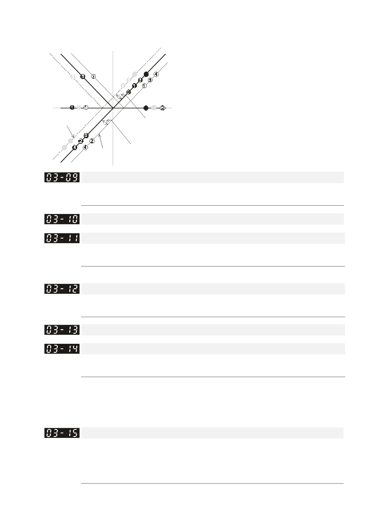
03-09~03-11 gain is positive
4
Z er o bias
Serve bias as the center, lower than bias =bias
Serve bias as the center, greater than bias=bias
The absolute value of the bias voltage
while serving as the center (unipolar)
Serve bias as the center(unipolar)
bias
bias
Positive bias
N
egative bias
Analog Input Gain 1 (AUI1)
Control Mode
VF VFPG SVC FOCPG FOCPM Default: 100.0
Settings 0.0–500.0%
Analog Input Gain 1 (AUI2)
Control Mode
VF VFPG SVC FOCPG FOCPM Default: 100.0
Settings 0.0–500.0%
Pr.03-03–Pr.03-11 are used when the Frequency command source is the analog voltage/current signal.
Analog Input Filter Time (AUI1)
Control Mode
VF VFPG SVC FOCPG FOCPM Default: 0.01
Settings 0.00–2.00 sec.
Analog Input Filter Time (AUI2)
Control Mode
VF VFPG SVC FOCPG FOCPM Default: 0.01
Settings 0.00–2.00 sec.
Analog signals, such as those entering AUI1 and AUI2, are commonly affected by interference that affects
the stability of the analog control. Use the Input Noise Filter to create a more stable system.
If Pr.03-14 is large, the control is more stable, but the response to the input is slower. If Pr.03-14 is small,
the control may be unstable, but the response to the input is faster.
Load Compensation Auto-tuning
Control Mode
VF VFPG SVC FOCPG
FOCPM Default: 0
Settings 0: No function
1: Auto-tunes with running without load
2: Auto-tunes with running with load
Use torque compensation function to avoid the roll-back generated by using IM to work with spiral gear.

 Loading...


