12 Descriptions of Parameter Settings | VFD-ED
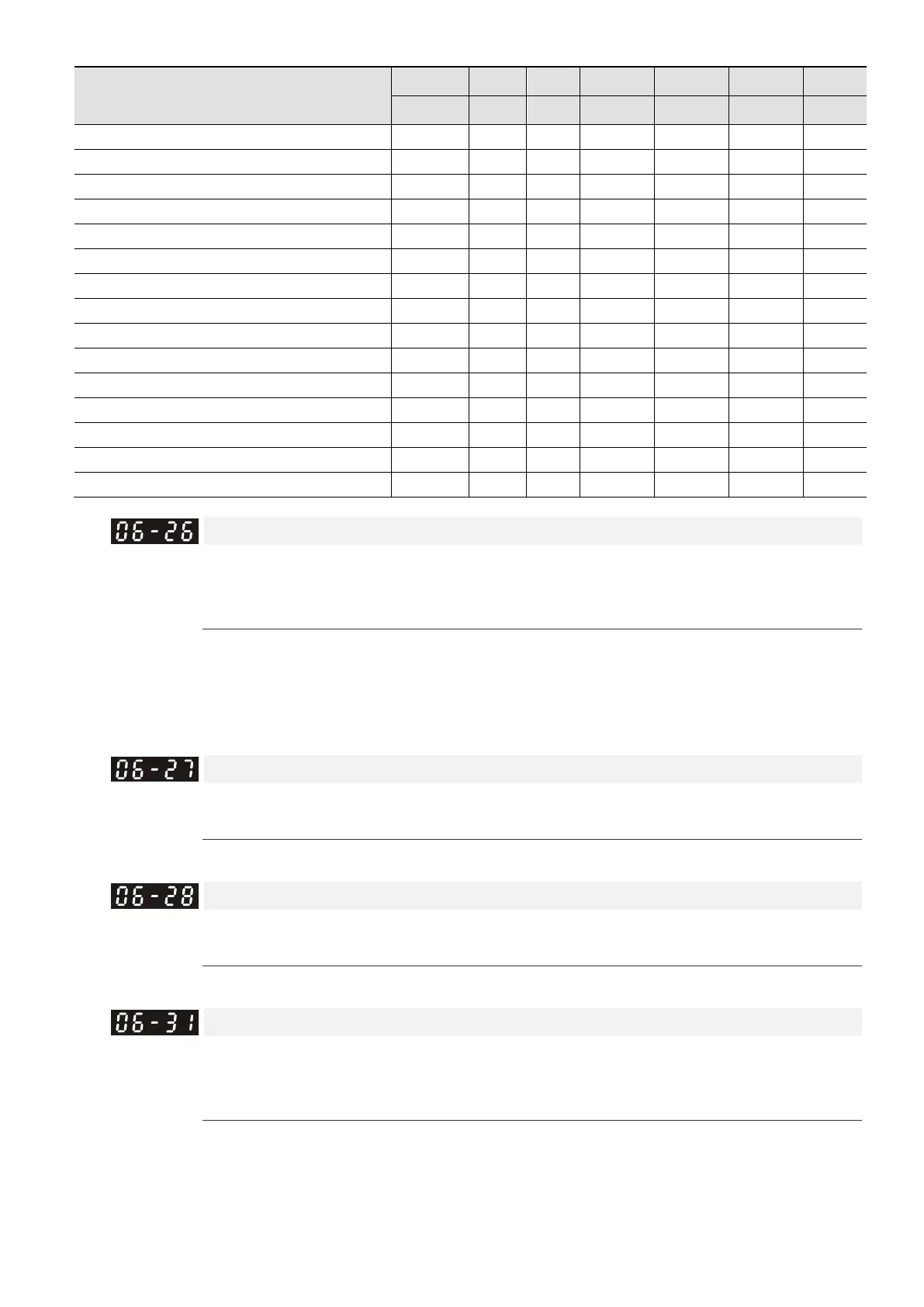
Fault Code
Bit0 Bit1 Bit2 Bit3 Bit4 Bit5 Bit6
current Volt. OL SYS FBK EXI CE
68: CAN BUS disconnected (CANF)
72: Safe torque loss (STL1)
73: PG cd hardware error (PGcd)
74: PG absolute signal error (PGHL)
75: PG Z phase signal loss (PGAF)
76: Safe torque output stops (STO)
77: Safe torque loss 2 (STL2)
78: Safe torque loss 3 (STL3)
82: U-phase output phase loss (OPHL)
83: V-phase output phase loss (OPHL)
84: W-phase output phase loss (OPHL)
86: Leveling switch short-circuited (LSS)
87: Leveling switch open-circuited (LSo)
95: BTTx Error (bttE) ●
PTC (Positive Temperature Coefficient) Detection Action
Control Mode
VF VFPG SVC FOCPG FOCPM Default: 0
Settings 0: Warn and keep operation
1: Fault and ramp to stop
Sets the action after detecting PTC.
When Pr.06-26 is set to 1 (Fault and ramp to stop), if brake or operation contactor is OFF under the
circumstance that STO or MI40 (Enable drive function) is not deactivated during deceleration, elevator still
runs even brake has engaged (brake wear), and electric arc occurs when operation contactor is OFF.
Control Mode
VF VFPG SVC FOCPG FOCPM Default: 50.0
Settings 0.0–100.0%
Sets the PTC level. 100% PTC level corresponds to the maximum analog input value.
PTC Detection Filter Time
Control Mode
VF VFPG SVC FOCPG FOCPM Default: 0.20
Settings 0.00–10.00 sec.
See Parameter Group 03 Analog Input/ Output Parameters for details.
Phase Loss Detection of Drive Output at Start-up (MPHL)
Control Mode
VF VFPG SVC FOCPG FOCPM Default: 1
Settings 0: Disable
1: Enable
1: Auto-detect whether the connection between the drive and motor is normal whenever the drive runs. If
an error occurs to the connection between the drive and the motor (broken or loose wiring) or there is no
output for the drive’s any or all of the three phases, the drive displays fault code “67” to indicate motor
output phase loss.

 Loading...


