12 Descriptions of Parameter Settings | VFD-ED
When Bit 7 = 1, zero speed position control is enabled (refer to Chapter 12 Parameter Group 02 Elevator
Timing Diagram). Pr.10-22 is valid only when bit 7 is set to 1, and this function only supports PM motors.
When Bit 9 = 1, valid only when Pr.10-00 is set to 3, and the mechanical brake must be in engaged status.
Elevator Speed
Control Mode
FOCPG FOCPM Default: 1.00
Settings 0.10–4.00 m/s
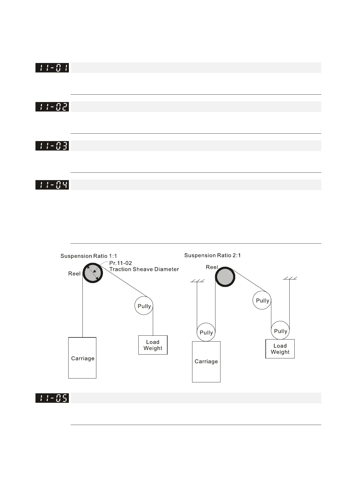
Traction Sheave Diameter
Control Mode
FOCPG FOCPM Default: 400
Settings 100–2000 mm
Gear Ratio
Control Mode
FOCPG FOCPM Default: 1.00
Settings 1.00–100.00
Suspension Ratio
Control Mode
FOCPG FOCPM Default: 1
Settings 0 = 1: 1
1 = 2: 1
2 = 4:1
3 = 8:1
Mechanical Inertial Ratio
Control Mode
FOCPG FOCPM Default: 40
Settings 1–300%
You can calculate the load inertia according to the settings of motor parameters, Pr.11-02 Traction
Sheave Diameter, Pr.11-14 Motor Current at Acceleration and Pr.11-15 Carriage Acceleration. You can
use this parameter to adjust the mechanical inertia ratio.
Mechanical inertia reference value (%):

 Loading...


