Chapter 6 Optional Accessories | VFD-ED
AC Output Reactor
When using drives in long wiring output application, ground fault (GFF), over-current (OC) and
motor over-voltage (OV) often occur. GFF and OC cause errors due to the drives self -protective
mechanism; over-voltage damages motor insulation.
The excessive length of the output wires makes the grounded stray capacitance too large, increase
the three-phase output common mode current, and the reflected wave of the long wires makes the motor
dv / dt and the motor terminal voltage too high. Thus, installing a reactor on the drive’s output side can
increases the high-frequency impedance to reduce the dv / dt and terminal voltage to protect the motor.
Installation
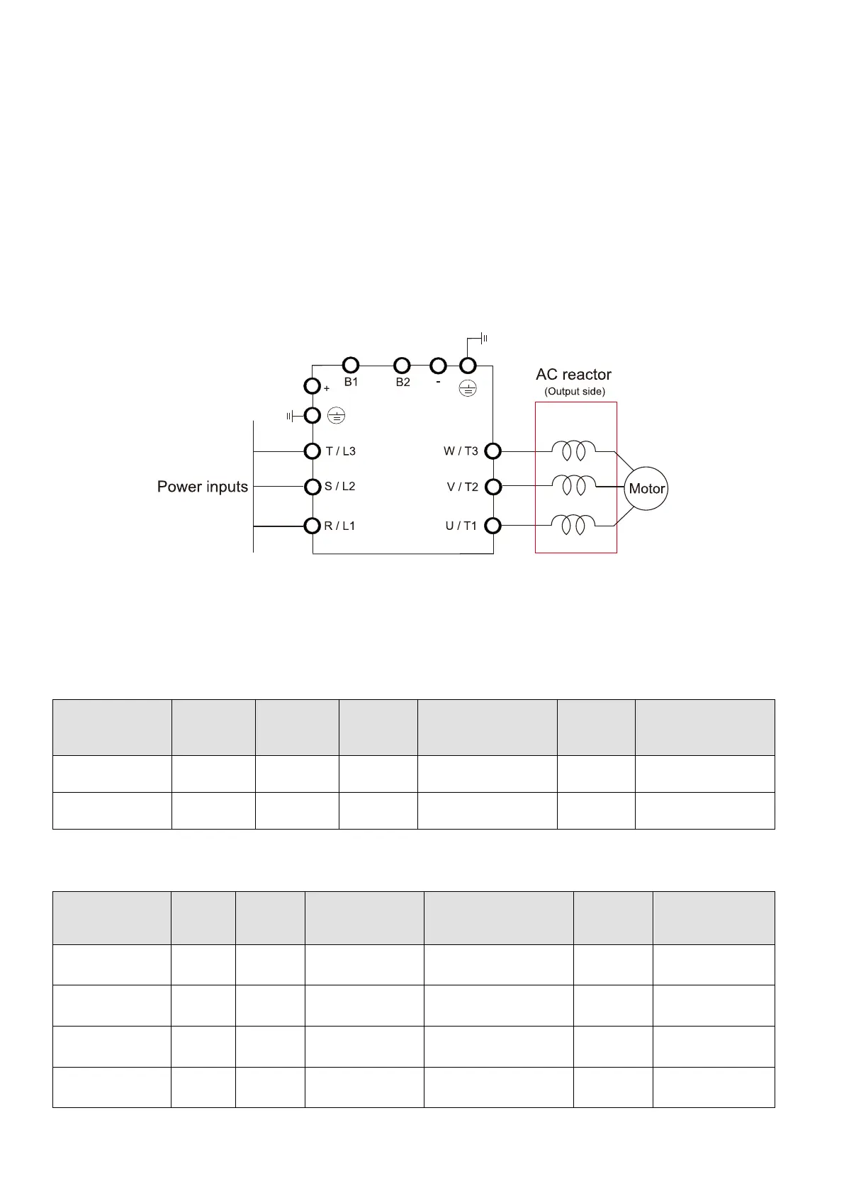
Install an AC output reactor in series between the three output phases U V W and the motor, as shown
in the figure below:
Figure 6-6 Connecting an AC Output Reactor
Applicable Reactors
200V–230V / 50–60 Hz (Single-phase power)
Model
Rated
Current
(Arms)
Saturation
Current
(Arms)
AC Input
Reactors
(mH)
AC Input Reactors
(Delta Part#)
AC Output
Reactors
(mH)
AC Output Reactors
(Delta Part #)
VFD022ED21S 12 24 1.172 DR025D0117 2.02 DR012L0202
VFD037ED21S 17 34 0.574 DR049DP574 1.17 DR018L0117
Table 6-8
200V–230V / 50–60 Hz (Three-phase power)
Model
Current
Current
Output Reactors
Reactors
Reactors
4% DC Reactors
(Delta Part #)
VFD040ED23 20 40 0.507
DR025AP507
DR025LP507
NA* NA*
VFD055ED23 24 48 0.507
DR025AP507
DR025LP507
1.17 DR025D0117
VFD075ED23 30 60 0.32
DR033AP320
DR033LP320
0.851 DR033DP851
VFD110ED23 45 90 0.215
DR049AP215
DR049LP215
0.574 DR049DP574

 Loading...


