Chapter 6 Optional Accessories | VFD-ED
Reactor Model *
1
Recommended Wire Size
Wiring
Method
Qty Applicable Motor Drives
RF008X00A
T60006L2040W453
≤ 8 AWG ≤ 8.37 mm
2
Fig. 6-32
Fig. 6-33
1
VFD022ED21S VFD037ED21S
VFD040ED23S VFD040ED43S
RF004X00A
T60006L2050W565
≤ 4 AWG ≤ 21.15 mm
2
Fig. 6-32
Fig. 6-33
1
VFD055ED23S VFD075ED23S
VFD110ED23S VFD055ED43S
VFD075ED43S VFD110ED43S
VFD150ED43S VFD185ED43S
RF002X00A
T60006L2160V066
≤ 2 AWG ≤ 33.62 mm
2
Fig. 6-32
Fig. 6-33
1
VFD150ED23S VFD185ED23S
VFD220ED23S VFD220ED43S
VFD300ED43S
RF300X00A
T60006L2160V066
≤ 300 MCM ≤ 152 mm
2
Fig. 6-32
Fig. 6-33
1
VFD300ED23S VFD370ED23S
VFD370ED43S VFD450ED43S
VFD550ED43S VFD750ED43S
*
1
: 600V insulated cable wire Table 6-36
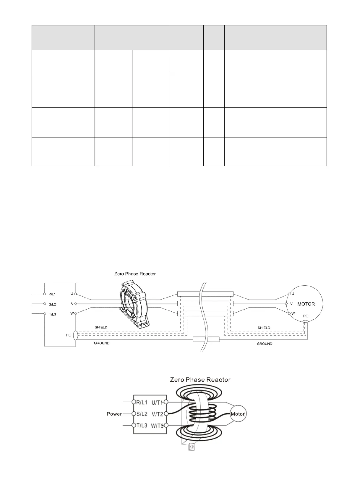
Installation
During installation, pass the cable through at least one zero phase reactor. Use a suitable cable type
(insulation class and wire section) so that the cable passes easily through the zero phase reactor. Do not
pass the grounding cable through the zero phase reactor; only pass the motor wire through the zero
phase reactor. With longer motor cables the zero-phase reactor can effectively reduce interference at the
motor output. Install the zero-phase reactor as close to the output of the drive as possible. Diagram A
shows the installation diagram for a single turn zero phase reactor. If the wire diameter allows several
turns, Diagram B shows the installation of a multi-turn zero phase reactor. The more turns, the better the
noise suppression effect.
Figure 6-32 Single turn wiring diagram for shielding wire with a zero phase reactor
Figure 6-33 Multi-turn zero phase reactor

 Loading...


