Chapter 16 PLC Function ApplicationsMS300 (High Speed Model)
16-16
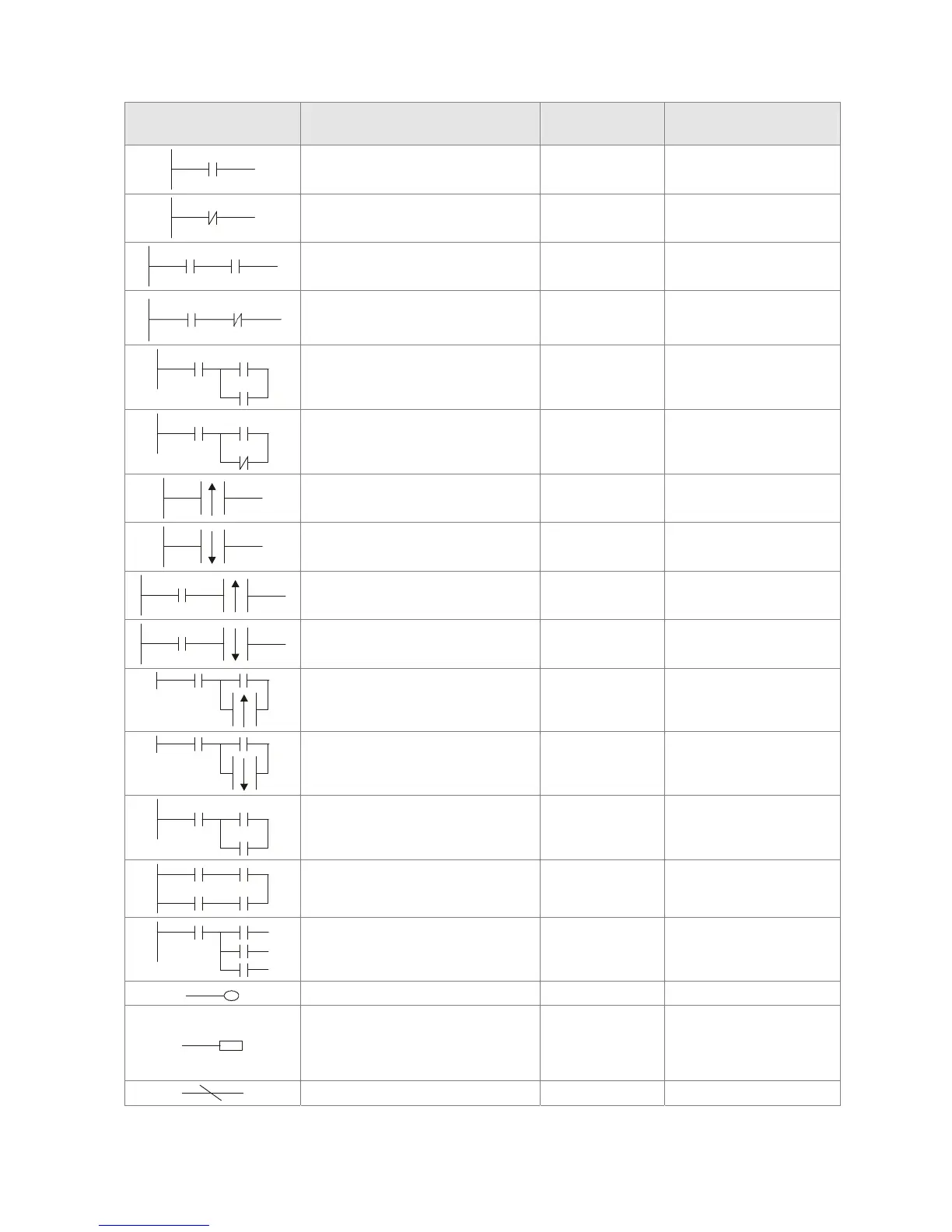
Ladder diagram images and their explanation
Ladder diagram
structures
Explanation of commands Command Using Device
NO switch, contact a LD
X、Y、M、T、C
NC switch, contact b LDI
X、Y、M、T、C
Series NO AND
X、Y、M、T、C
Series NC ANI
X、Y、M、T、C
Parallel NO OR
X、Y、M、T、C
Parallel NC ORI
X、Y、M、T、C
Positive edge-triggered switch LDP
X、Y、M、T、C
Negative edge-triggered switch LDF
X、Y、M、T、C
Positive edge-triggered series ANDP
X、Y、M、T、C
Negative edge-triggered series ANDF
X、Y、M、T、C
Positive edge-triggered parallel ORP
X、Y、M、T、C
Negative edge-triggered parallel ORF
X、Y、M、T、C
Block series ANB N/A
Block parallel ORB N/A
Multiple outputs
MPS
MRD
MPP
N/A
Coil driven output commands OUT
Y、M
Some basic commands,
applications commands
Some basic
commands
Applications
commands
Inverted logic INV N/A
 Loading...


