Chapter 16 PLC Function ApplicationsMS300 (High Speed Model)
16-17
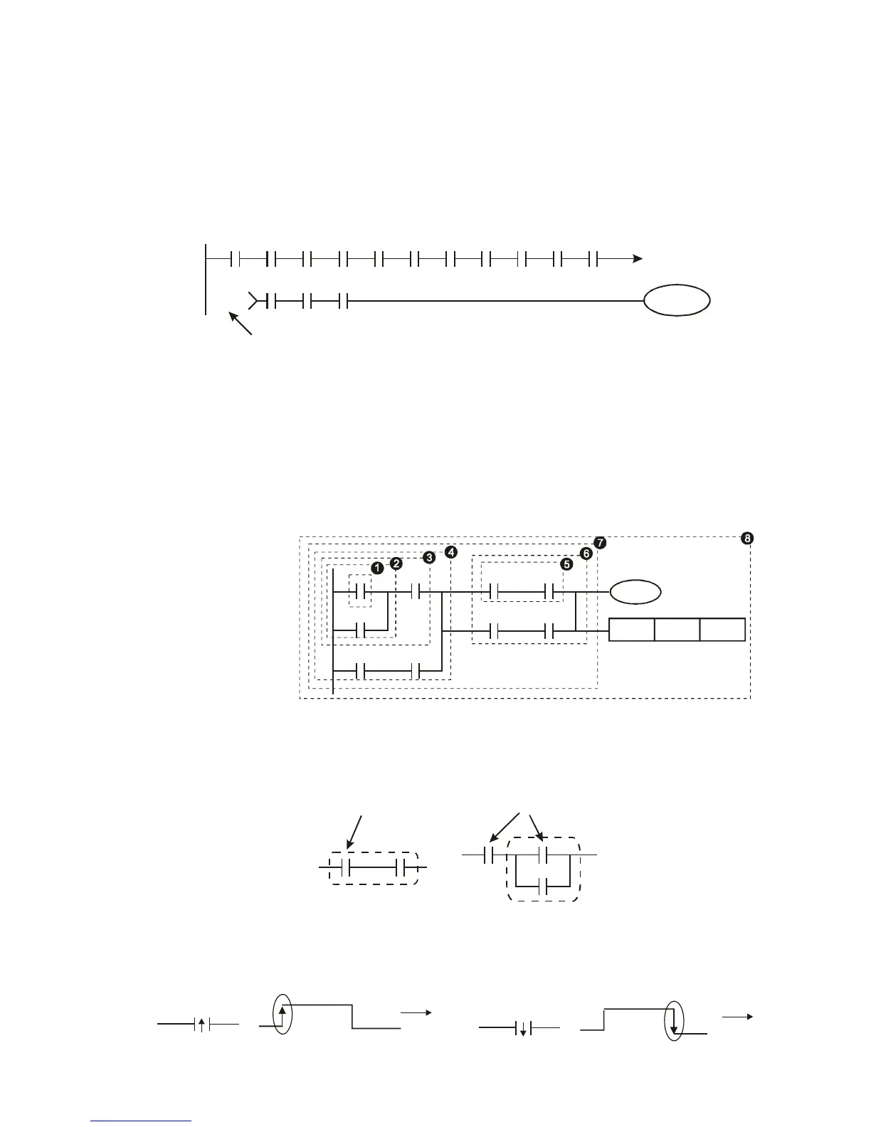
16-4-3 Overview of PLC ladder diagram editing
The program editing method begins from the left busbar and proceeds to the right busbar (the right
busbar is omitted when editing using WPLSoft). Continue to the next row after completing each row;
there is a maximum of 11 contacts on each row. If this is not sufficient, a continuous line will be will be
generated to indicate the continued connection and more devices can be added. A continuous series
of numbers will be generated automatically and identical input points can be used repeatedly. See
figure below:
X0 X1 X2 X3 X4 X5
Y0
X11 X12 X13
X6 X7 X10 C0 C1
00000
00000
Row Number
The ladder diagram programming method involves scanning from the upper left corner to the lower
right corner. The coils and applications command computing box are handled in the output, and the
ladder diagram is placed on the farthest right. Taking the figure below as an example, we can
gradually analyze the procedural sequence of the ladder diagram. The number in the upper right
corner gives the sequential order.
Explanation of
command sequence
X0 X1 Y1 X4
M0
X3
M1
T0
M3
Y1
TMR
T0
K10
1 LD X0
2 OR M0
3 AND X1
4 LD X3
AND M1
ORB
5 LD Y1
AND X4
6 LD T0
AND M3
ORB
7 ANB
8 OUT Y1
TMR T0 K10
Explanation of basic structure of ladder diagrams
LD (LDI) command: An LD or LDI command is given at the start of a block.
AND Block OR Block
LD command LD command
LDP and LDF have this command structure, but there are differences in their action state. LDP, LDF
only act at the rising or falling edge of a conducting contact. (See figure below):
X0
OFF
ON
OFF
Time
Falling-edge
X0
OFF
ON
OFF
Time
Rising-edge
 Loading...


