Chapter 16 PLC Function ApplicationsMS300 (High Speed Model)
16-21
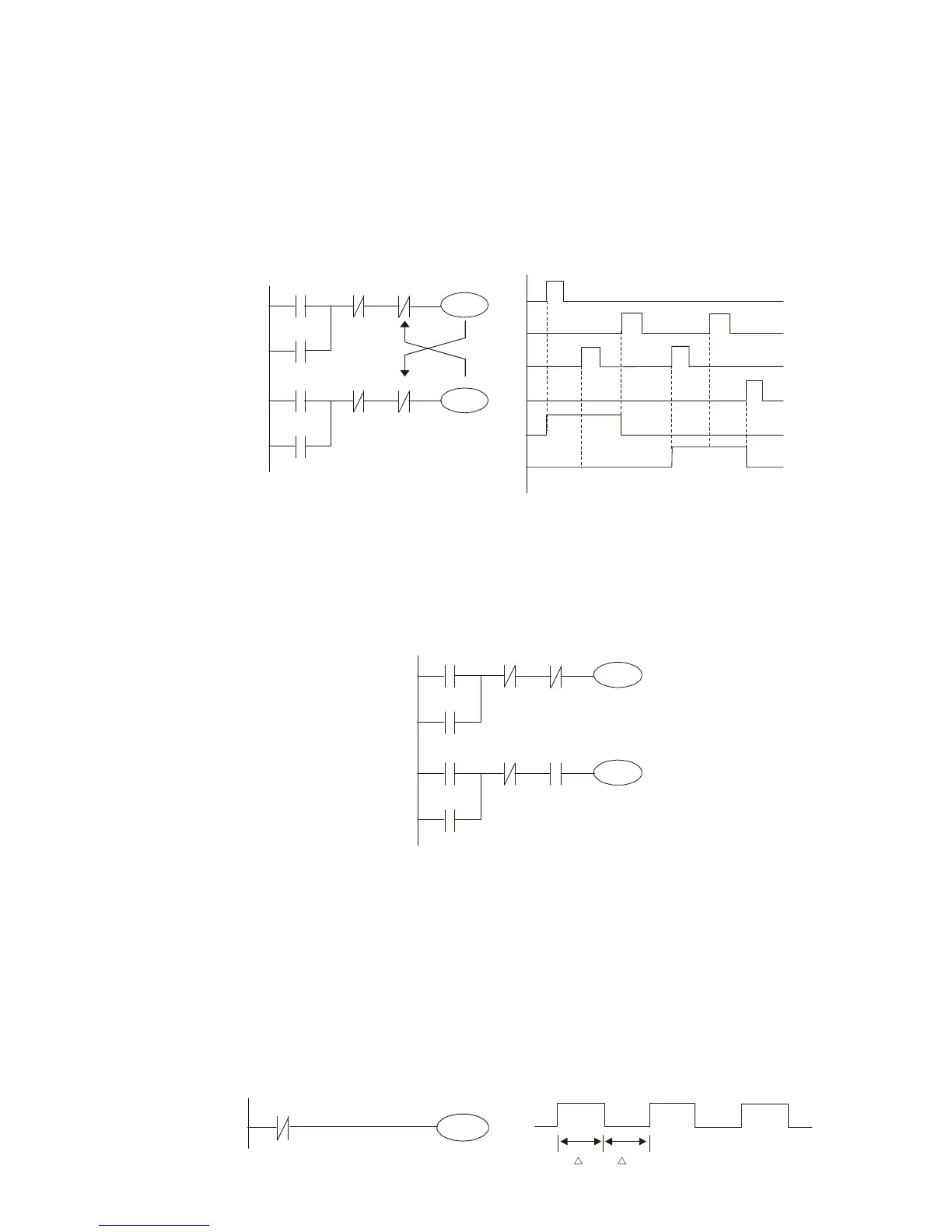
Example 5: Interlocking control
The figure below shows an interlocking control circuit. Depending on which of the start
contacts X1, X2 is valid first, the corresponding output Y1 or Y2 will be actuated, and
when one is actuated, the other will not be actuated. This implies that Y1 and Y2 cannot
be actuated at the same time (interlocking effect). Even if both X1 and X2 are valid at the
same time, because the ladder diagram program is scanned from the top down, it is
impossible for Y1 and Y2 to be actuated at same time. This ladder diagram assigns
priority only to Y1.
X1
X3
Y1
Y1
X2
X4
Y2
Y2
Y1
X1
X3
X2
X4
Y1
Y2
Y2
Example 6: Sequence control
If the NC contact of Y2 in the interlocking control configuration of example 5 is put in
series with the Y1 circuit, so that it is an AND condition for actuation of Y1 (see figure
below), not only is Y1 a condition for the actuation of Y2 in this circuit, the actuation of Y2
will also stop the actuation of Y1. This configuration confirms the actuation order of Y1
and Y2.
X1
X3
Y1
Y1
X2
X4
Y2
Y2
Y1
Y2
Example 7: Oscillating circuit
Oscillating circuit with a period of ∆T+∆T
The figure below shows a very simple ladder diagram. When starting to scan the Y1 NC
contact, because the Y1 coil has lost power, the Y1 NC contact will be closed. When the
Y1 coil is then scanned, it will be electrified, and the output will be 1. When the Y1 NC
contact is scanned in the scanning cycle, because Y1 coil is electrified, the Y1 NC
contact will be open, the Y1 coil will then lose power, and the output will be 0. Following
repeated scanning, the output of Y1 coil will have an oscillating waveform with a period
of ∆T(On)+∆T(Off).
Y1
Y1
Y1
T T
 Loading...


