Chapter 16 PLC Function ApplicationsMS300 (High Speed Model)
16-22
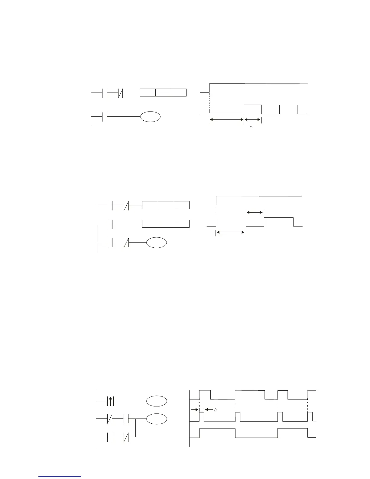
Oscillating circuit with a period of nT+∆T
The program of the ladder diagram shown below uses timer T0 to control coil Y1's electrified
time. After Y1 is electrified, it causes timer T0 to close during the next scanning cycle, which
will cause the output from Y1 to have the oscillating waveform shown in the figure below.
Here n is the timer's decimal setting value, and T is the clock cycle of the timer.
T0
Y1
Y1
nT
T
TMR
T0 Kn
X0
Y1
X0
Example 8: Flashing circuit
The following figure shows an oscillating circuit of a type commonly used to cause an
indicator light to flash or a buzzers to buzz. It uses two timers to control the On and Off
time of Y1 coil. Here n1, n2 are the timing set values of T1 and T2, and T is the clock
cycle of the timer.
T1
Y1
Y1
n1*T
TMR
T1 Kn1
X0
T2
X0
TMR
T2 Kn2
T1
X0
n2*T
Example 9: Triggering circuit
In the figure below, a command consisting of the differential of the rising edge of X0
causes coil M0 to generate a single pulse for ∆T (length of one scanning cycle), and coil
Y1 is electrified during this scanning cycle. Coil M0 loses power during the next scanning
cycle, and NC contact M0 and NC contact Y1 are both closed. This causes coil Y1 to stay
in an electrified state until there is another rising edge in input X0, which again causes the
electrification of coil M0 and the start of another scanning cycle, while also causing coil
Y1 to lose power, etc. The sequence of these actions can be seen in the figure below.
This type of circuit is commonly used to enable one input to perform two actions in
alternation. It can be seen from the time sequence in the figure below that when input X0
is a square wave signal with a period of T, the output of coil Y1 will be a square wave
signal with a period of 2T.
X0
M0
X0
Y1M0
M0
Y1
Y1
M0
Y1
T
 Loading...


