Chapter 16 PLC Function ApplicationsMS300 (High Speed Model)
16-23
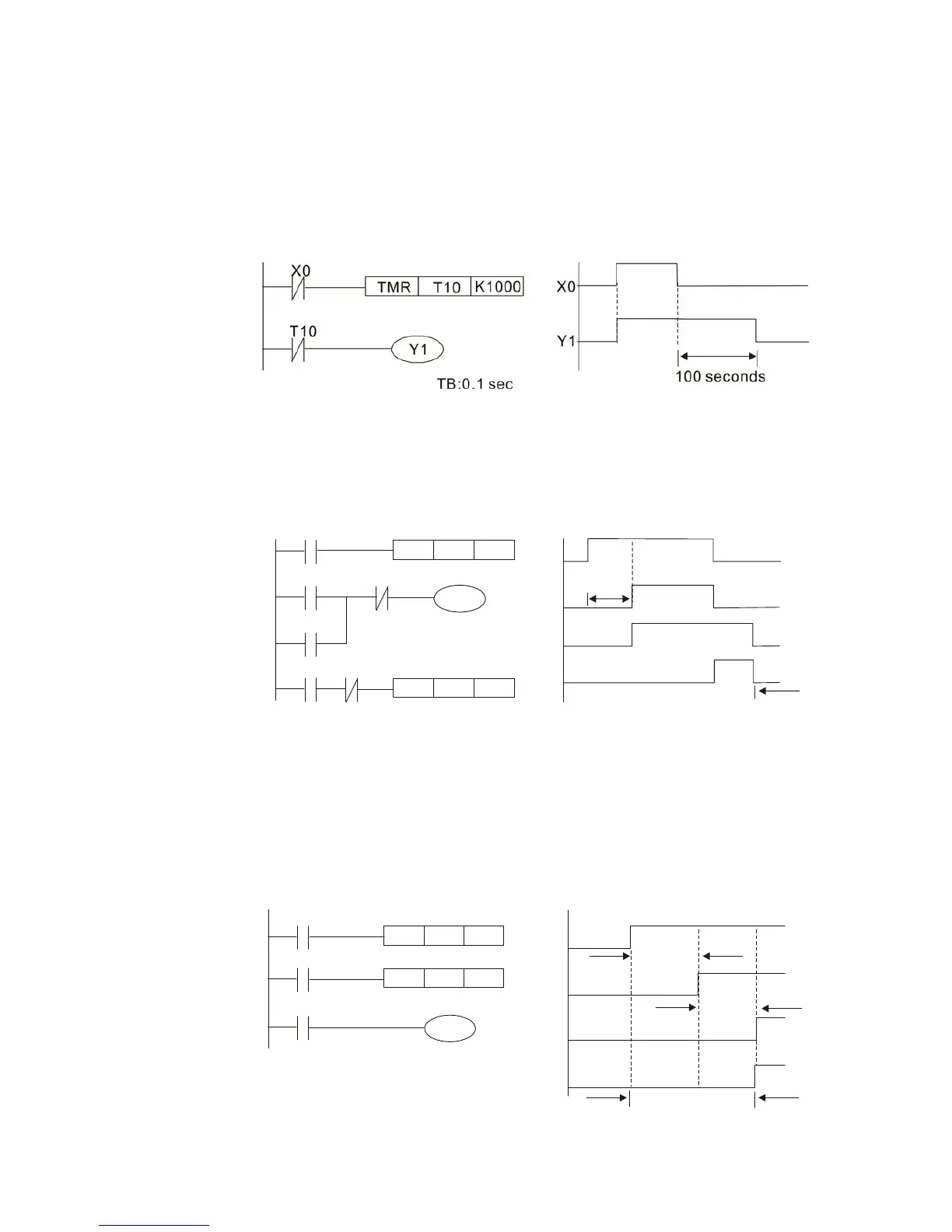
Example 10: Delay circuit
When input X0 is On, because the corresponding NC contact will be Off, the timer T10
will be in no power status, and output coil Y1 will be electrified. T10 will receive power
and begin timing only after input X0 is Off, and output coil Y1 will be delayed for 100 sec.
(K1000*0.1 sec. =100 sec.) before losing power; please refer to the sequence of actions
in the figure below.
Example 11: The open/close delay circuit is composed of two timers; output Y4 will have a delay
whether input X0 is On or Off.
X0
Y4
TMR
T6
K30
X0
X0
Y4
TMR
T5
K50
T6
T5
3
秒
Y4
T5
T6
5
秒
Y4
Example 12: Extended timing circuit
In the circuit in the figure on the left, the total delay time from the moment input X0
closes to the time output Y1 is electrified is (n1+n2)*T, where T is the clock cycle.
Timers: T11, T12; clock cycle: T.
X0
Y1
TMR T12
Kn2
X0
T11
TMR
T11
Kn1
T12
Y1
T11
T12
n1*T
n2*T
(n1+n2)*T
5
seconds
3 seconds
 Loading...


