NO.3 Wiring
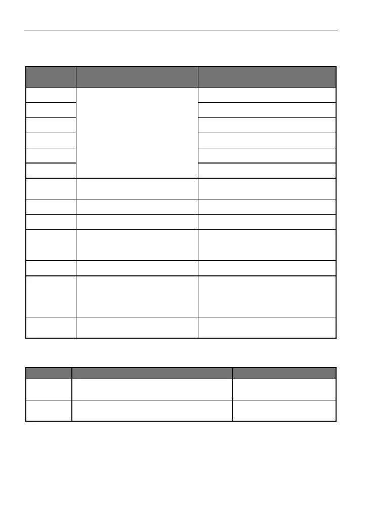
3.4 Description of control terminals
Multi-function digital input
terminals 1-6
Set as forward during delivery
Set as reverse during delivery
Set as reset during delivery
Set as high speed during delivery
Set as medium speed during delivery
Set as low speed during delivery
Digital/analog/communication
and power earthing terminals
Isolation of GND inside from PE
Maximum output current: 150mA
Input voltage range: 0-+10V
Analog current/voltage input,
selecting via jumper1, default to
current input
Input current range: 0-+20mA
Input voltage range: 0-+10V
Output voltage range: 0-+10V
Multi-function relay output
FA-FC: normally open, FB-FC:
normally closed
Contact specification: 250VAC/3A,
30VDC/3A
RS485 communication interface
Available connection of 1-32 RS485
sites
3.5 Description of jumper function
Selection of AI2 input type
V: Voltage mode mA: Current mode
Selection of X1-X6 wiring mode
NPN type or PNP type
Wiring mode of multi-function digital input terminals X1-X6:
(1) When NPN type wiring mode is adopted for external equipment, leakage type logic is
induced and the current flows out from input terminal (sourcing current) as shown in Figure
3-1, at the same time parameter P067=0 is required.
 Loading...