EasyManuals Logo

DEMA D6B Series User Manual

DEMA D6B Series
99 pages
To Next Page IconTo Next Page
To Previous Page IconTo Previous Page
Page #93 background imageLoading...
Page #93 background image
Annex
89
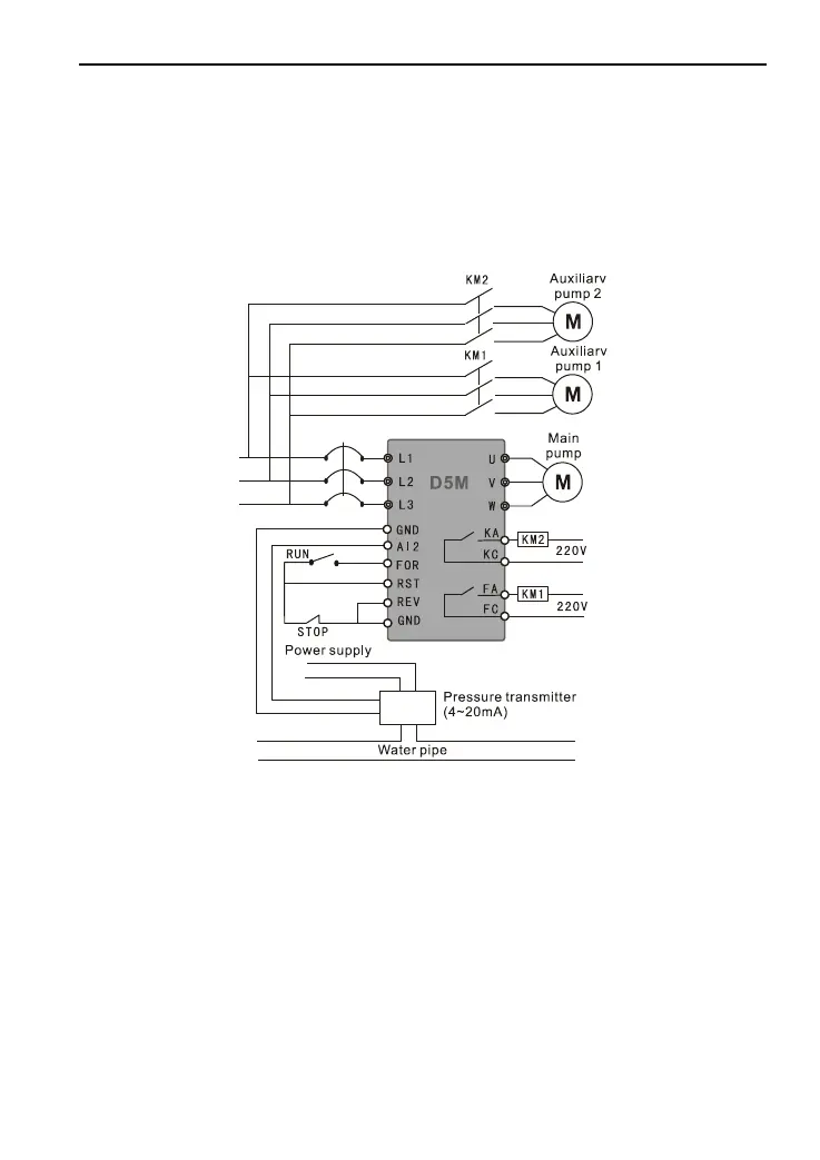
(3) Wiring diagram and parameters of single-machine and multi-pump are shown in Figure
F-7.
Parameter setting
P001=1
P014=*
P015=*
P023=0
P026=1
P041=*
P045=25
P046=04
P053=8
P060=*
P130=1
P156=*
P157=*
P158=*
P159=*
Figure F-7 Single-machine and Multi-pump Wiring Diagram
6. Cases of joint application of analog and multi-segment speed
Requirements: Set the frequency of the first segment speed via analog; after switching via a
switch, switch to external multi-segment speed for operating. Wiring is as shown in Figure
F-8.
Parameter setting
P002=1
P081=2
P047=20
P048=21
P086=15
P087=30
P088=25

Table of Contents

Questions and Answers:

Question and Answer IconNeed help?

Do you have a question about the DEMA D6B Series and is the answer not in the manual?

DEMA D6B Series Specifications

General IconGeneral
BrandDEMA
ModelD6B Series
CategoryInverter
LanguageEnglish

Related product manuals