D1000 Installation and Service Manual 6
Home LAB-110073 Rev. 3
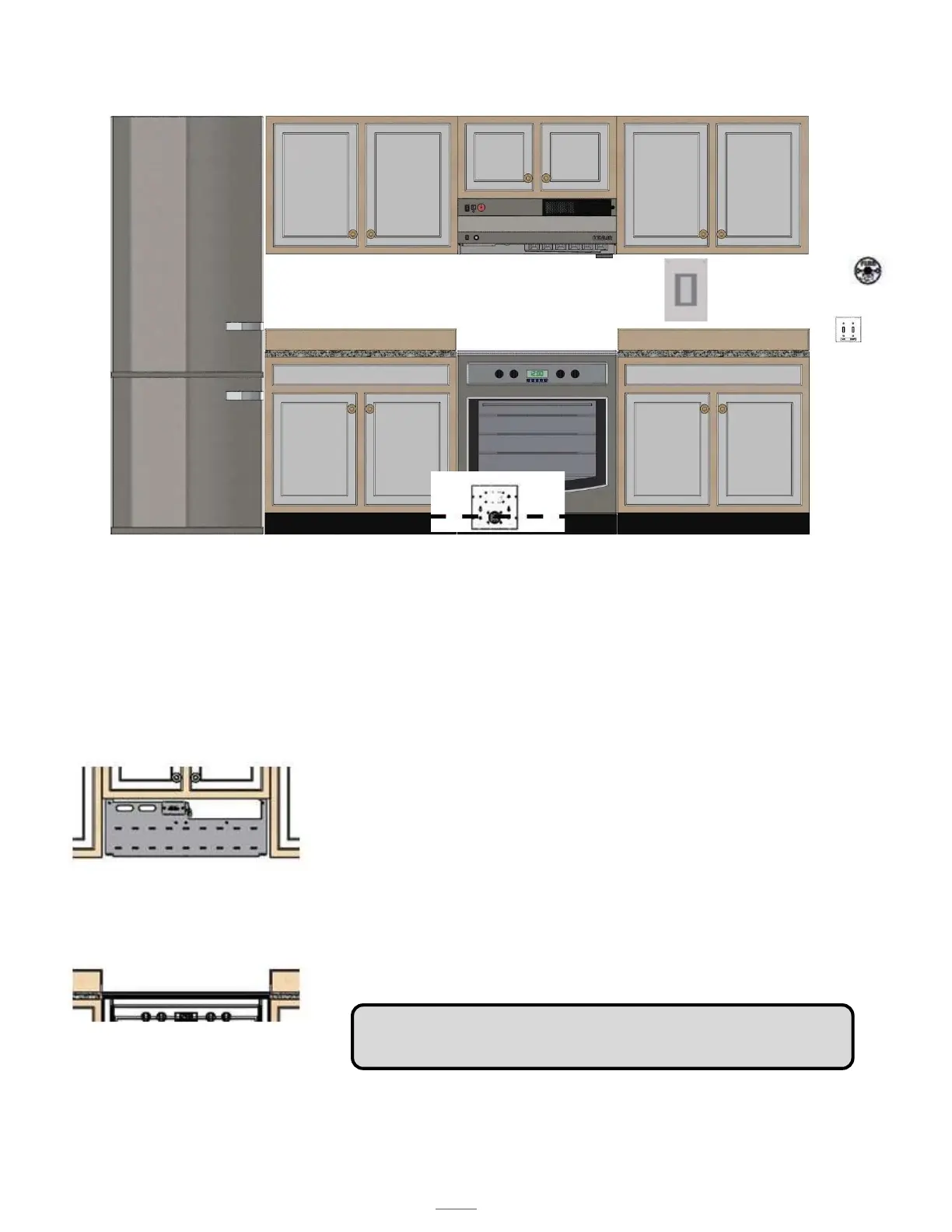
PREPARING THE INSTALL LOCATION
Note# 1: If cabinets are not present in the space, a Top Cover is required (option D1030 -TC I or F/R or D1036-TC I or F/R)
Note #2: Center the D1000 over the range. If the range is not in place, the center marking should be relative to its final
Position.
Note #3: Refer to the model specific engineered submittal sheet for the exact measurements which are not represented
here (available at denlarhoods.com)
Note #4: Refer to “Installing the D1000” (on page 17) for instructions on attaching the D1000 to the mounting
bracket
Note #5: Refer to option specific schematics for more details on how to connect them to the D1000
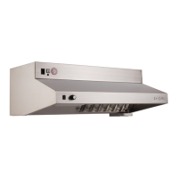
Note # 6: As indicated on page 7, allow for 4 5/8” between the top of the mounting bracket and the bottom of the
cabinet above. In order to allow the installation of the NFPA101 compliant version of the D1000-F/R, which uses an
additional Fan Box as shown attach the fan box to the bracket, and then proceed.
NOTE # 5 COMPONENTS
E
A
B
F
G
A. DENLAR D1000 (30” or 36”)
B. Range (for reference purposes (gas, electric or dual element, dual
receptacle)
C. Electric Power disconnect (shown)
D. Gas Power Disconnect (not shown)
E. The CLOCKBOX- range element lockout system (CLBX option) The
Touchscreen (E) is shown, the control module is not shown.
F. Handicap Accessible Control Box (ADA option)
G. Manual Pull Station (MPK option)
Note: The dual element disconnect (DED option) integrates both the
electric and gas power disconnect options.
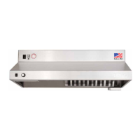
View of Mounting Bracket Installed