EasyManua.ls Logo

Denon AVR-1609 Service Manual

Denon AVR-1609
148 pages
To Next Page IconTo Next Page
Page #1 background imageLoading...
Page #1 background image
Denon Brand Company, D&M Holdings lnc.
e
Ver. 1
SERVICE MANUAL
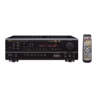
AV SURROUND RECEIVER
MODEL JP E3 E2 EK E2A E1C EA
AVR-1709
33 3
AVR-1609
3
AVR-1519
3
AVR-1509
33
AVR-689
33
AVR-589
33
AVC-1509
3
For purposes of improvement, specifications and
design are subject to change without notice.
Please use this service manual with referring to the
operating instructions without fail.
Some illustrations using in this service manual are
slightly different from the actual set.
注 意
サービスをおこなう前に、このサービスマニュアル
を必ずお読みください。本機は、火災、感電、けが
などに対する安全性を確保するために、さまざまな
配慮をおこなっており、また法的には「電気用品安
全法」にもとづき、所定の許可を得て製造されてお
ります。従ってサービスをおこなう際は、これらの
安全性が維持されるよう、このサービスマニュアル
に記載されている注意事項を必ずお守りください。
本機の仕様は性能改良のため、予告なく変更すること
があります。
補修用性能部品の保有期間は、製造打切後 8 年です。
修理の際は、必ず取扱説明書を参照の上、作業を行っ
てください。
本文中に使用しているイラストは、説明の都合上現物
と多少異なる場合があります。
X0382 V.01 DE/CDM 0806
w
w
w
.
x
i
a
o
y
u
1
6
3
.
c
o
m
Q
Q
3
7
6
3
1
5
1
5
0
9
9
2
8
9
4
2
9
8
T
E
L
1
3
9
4
2
2
9
6
5
1
3
9
9
2
8
9
4
2
9
8
0
5
1
5
1
3
6
7
3
Q
Q
TEL 13942296513 QQ 376315150 892498299
http://www.xiaoyu163.com
Table of Contents

Other manuals for Denon AVR-1609

Questions and Answers:

Denon AVR-1609 Specifications

General IconGeneral
Channels7.1
HDMI Inputs3
HDMI Outputs1
Network ConnectivityNo
Response Bandwidth10 Hz - 100 kHz
Signal-To-Noise Ratio100 dB
Total Harmonic Distortion0.08%
Input Sensitivity200 mV
Digital Optical Inputs2
Digital Optical Output1
Digital Coaxial Inputs2
Audio Formats SupportedDolby Digital, Dolby Digital Plus, Dolby TrueHD, DTS, DTS-HD Master Audio
Video Formats Supported1080p
Input Impedance47 kOhms
Dimensions (W x H x D)434 x 151 x 319 mm
Power Output75W (8 ohms, 20 Hz - 20 kHz, 0.08% THD, 2 channels driven)

Summary

SAFETY PRECAUTIONS

LEAKAGE CURRENT CHECK

Checks for leakage current or line-to-chassis resistance before customer return.

Heed the cautions!

Pay attention to labels/seals and handling instructions for safe servicing.

Caution concerning electric shock!

Avoid electric shock by using safety precautions with internal metal parts.

Caution concerning disassembly and assembly!

Use gloves to protect hands from potential burrs on sheet metal parts.

Only use designated parts!

Use specified replacement parts, especially those marked with 'z' for safety.

Be sure to mount parts and arrange the wires as they were originally!

Restore parts and wiring to original positions for safety and performance.

Inspect for safety after servicing!

Verify all parts, connections, and perform insulation checks after servicing.

Concerning important safety parts

Parts with safety properties are marked 'z' on diagrams; use designated replacements.

DIMENSIONS - AVR-1709 Model

DIMENSIONS - AVR-1609/1509/1519 Model

DIMENSIONS - AVR-689 Model

DIMENSIONS - AVR-589 Model

WIRE ARRANGEMENT

DISASSEMBLY

PANEL FRONT SUB ASSY

Disassembly steps for the front panel sub assembly.

HDMI P.W.B.ASSY

Disassembly steps for the HDMI P.W.B. assembly.

SIRIUS P.W.B ASSY

Disassembly steps for the Sirius P.W.B. assembly.

TUNER PACK

Disassembly steps for the tuner pack.

SPEAKER P.W.B ASSY

Disassembly steps for the speaker P.W.B. assembly.

CHASSIS BACK SUB ASSY

Disassembly steps for the chassis back sub assembly.

VIDEO P.W.B ASSY

Disassembly steps for the video P.W.B. assembly.

INPUT / CPU P.W.B ASSY

Disassembly steps for the input/CPU P.W.B. assembly.

MAIN P.W.B SUB ASSY

Disassembly steps for the main P.W.B. sub assembly.

POWER P.W.B SUB ASSY

Disassembly steps for the power P.W.B. sub assembly.

TRANS

Disassembly steps for the transformer unit.

CAUTION IN SERVICING

Initializing AV SURROUND RECEIVER/AMPLIFIER

Procedure for initializing the AV receiver/amplifier after component replacement.

JIG to use for servicing

Lists jigs required for servicing, including extension cable kits and firmware update tools.

Check mode for µcom/DSP version

µcom/DSP version display mode

Specifies how to display µcom/DSP version information upon startup.

Display Order

Defines the order of information displayed: destination, main µcom, and DSP versions.

PROCEDURE FOR CHECKING ERRORS (Displaying the protection history)

Errors checking mode (Displaying the protection history)

Details on entering and operating the error history display mode.

About the display on the FL display

Explains how protection history is displayed on the FL display.

Clearing the protection history

Describes two methods for clearing the protection history.

Warning indication by the POWER LED

Explains POWER LED warnings for ASO/DC and Thermal protection incidents.

ADJUSTMENT

Audio Section

Covers adjustments for the audio section, including idling current and presets.

TROUBLE SHOOTING

Power Issues

Troubleshooting for power-related problems, including not turning on and blown fuses.

Analog Video - AVR-1709 Troubleshooting

No Picture or Sound Output

Steps to diagnose and resolve no picture/sound issues for AVR-1709 analog video.

Analog Video - AVR-1609 Troubleshooting

No Picture or Sound Output

Steps to diagnose and resolve no picture/sound issues for AVR-1609 analog video.

HDMI/DVI Connectivity

Troubleshooting No Picture or Sound Output

Steps to diagnose and resolve issues with no picture or sound from HDMI/DVI connections.

Block Diagrams

Audio Block Diagram - AVR-1709/689

Schematic of the audio signal flow for AVR-1709 and AVR-689 models.

Audio Block Diagram - AVR-1609/1509/589, AVC-1509

Schematic of the audio signal flow for AVR-1609, AVR-1509, AVR-589, AVC-1509 models.

Video Block Diagram - AVR-1709/689

Schematic of the video signal path for AVR-1709 and AVR-689 models.

Video Block Diagram - AVR-1609/1509/589, AVC-1509

Schematic of the video signal path for AVR-1609, AVR-1509, AVR-589, AVC-1509 models.

Level Diagrams

Front Channel Level Diagram

Diagram illustrating signal levels for the front audio channels.

Center Channel Level Diagram

Diagram illustrating signal levels for the center audio channel.

Subwoofer Channel Level Diagram

Diagram illustrating signal levels for the subwoofer audio channel.

Surround Channel Level Diagram

Diagram illustrating signal levels for the surround audio channels.

Surround Back Channel Level Diagram

Diagram illustrating signal levels for the surround back audio channels.

Semiconductors

ICs

Details on integrated circuits, including pin functions for M30626FHPFP.

ADSP21367 IC Terminal Functions

Pin configuration and terminal functions for the ADSP21367 integrated circuit.

R2A15215FP IC Block Diagram and Functions

Block diagram and terminal functions for the R2A15215FP IC.

W9864G2GH-6 IC Block Diagram

Block diagram for the W9864G2GH-6 integrated circuit.

LC87F6D16A IC

Details on the LC87F6D16A integrated circuit, including pin functions.

Sil9185 IC Block Diagram

Block diagram and pin functions for the Sil9185 HDMI interface IC.

ADV7180BSTZ IC

Details for the ADV7180BSTZ IC, including pin functions and block diagram.

ADV7172KSTZ IC

Details for the ADV7172KSTZ IC, including block diagram.

ADAU1328 IC Pin Function

Pin functions for the ADAU1328 audio codec IC.

LC89057W IC Block Diagram and Terminal Functions

Block diagram and terminal functions for the LC89057W IC.

NJW1321 IC Block Diagram

Block diagram for the NJW1321 IC used in AVR-1709/689 models.

EN29LV160AB-70TI IC Block Diagram

Block diagram for the EN29LV160AB-70TI Flash Memory IC.

LA73053 IC

Details on the LA73053 IC, including its block diagram and functions.

BH7868 IC

Details on the BH7868 IC for AVR-1709/689 models.

NJM2585 IC

Details on the NJM2585 IC for AVR-1609/1509/589, AVC-1509 models.

LC72722 IC Block Diagram

Block diagram for the LC72722 IC used in AVR-1709/1509 E2 models.

SN74LCX244 IC

Pin functions for the SN74LCX244 IC.

SN74HCT244 IC

Pin functions for the SN74HCT244 IC.

BU2092 IC

Details on the BU2092 IC.

BU2090F IC

Details on the BU2090F IC.

BA7625 IC

Details on the BA7625 IC for AVR-1709/689 and AVR-1609/1509/589, AVC-1509 models.

BU4094BCF IC

Details on the BU4094BCF IC.

BU4052 IC

Details on the BU4052 IC for AVR-1709/689 and AVR-1509 models.

74LVX157MTC IC

Details on the 74LVX157MTC IC.

FL Display

HNA-16SM13T Module (FL301)

Information and pin assignments for the HNA-16SM13T FL display module.

Printed Wiring Boards

Main P.W.B. Unit

Component and foil side layouts for the main printed wiring board.

Front P.W.B. Unit (1/2)

Component and foil side layouts for the first part of the front P.W.B. unit.

Front P.W.B. Unit (2/2)

Component and foil side layouts for the second part of the front P.W.B. unit.

Input P.W.B. Unit

Component and foil side layouts for the input printed wiring board.

Power P.W.B. Unit (1/2)

Component side layout for the first part of the power P.W.B. unit.

CPU P.W.B. Unit

Component and foil side layouts for the CPU printed wiring board.

HDMI P.W.B. Unit

Component and foil side layouts for the HDMI printed wiring board.

Video P.W.B. Unit (1/2) - AVR-1709/689

Component side layout for the first part of the video P.W.B. unit for AVR-1709/689.

Video P.W.B. Unit (2/2) - AVR-1709/689

Foil side layout for the second part of the video P.W.B. unit for AVR-1709/689.

D-Video P.W.B. Unit (1/2) - AVR-1609/1509/589, AVC-1509

Component side layout for the first part of the D-Video P.W.B. unit.

D-Video P.W.B. Unit (2/2) - AVR-1609/1509/589, AVC-1509

Foil side layout for the second part of the D-Video P.W.B. unit.

2CH Amp P.W.B. Unit - AVR-1709/1609/689

Component and foil side layouts for the 2CH Amp P.W.B. unit.

Power P.W.B. Unit - AVR-1519/1509/589, AVC-1509

Component and foil side layouts for the power P.W.B. unit.

Sirius P.W.B. Unit

Component and foil side layouts for the Sirius P.W.B. unit.

Parts List Notes

Resistor Identification

Explanation of resistor markings, types, and characteristics.

Capacitor Identification

Explanation of capacitor markings, types, and characteristics.

Parts List of P.W.B. Unit

Semiconductors Group

List of semiconductor components for the Main P.W.B. Unit, including part numbers and remarks.

Resistors Group

List of resistors for the Main P.W.B. Unit, including part numbers and remarks.

Capacitors Group

List of capacitors for the Main P.W.B. Unit, including part numbers and remarks.

Other Parts Group

List of miscellaneous parts like connectors, jacks, and relays for the Main P.W.B. Unit.

Front P.W.B. Unit Ass'y

Semiconductors Group

List of semiconductor components for the Front P.W.B. Unit.

Resistors Group

List of resistors for the Front P.W.B. Unit.

Capacitors Group

List of capacitors for the Front P.W.B. Unit.

Other Parts Group

List of miscellaneous parts like connectors, fuses, and knobs for the Front P.W.B. Unit.

Input P.W.B. Unit Ass'y

Semiconductors Group

List of semiconductor components for the Input P.W.B. Unit.

Resistors Group

List of resistors for the Input P.W.B. Unit.

Capacitors Group

List of capacitors for the Input P.W.B. Unit.

Power P.W.B. Unit Ass'y

Semiconductors Group

List of semiconductor components for the Power P.W.B. Unit.

Resistors Group

List of resistors for the Power P.W.B. Unit.

Capacitors Group

List of capacitors for the Power P.W.B. Unit.

CPU P.W.B. Unit Ass'y

Semiconductors Group

List of semiconductor components for the CPU P.W.B. Unit.

Resistors Group

List of resistors for the CPU P.W.B. Unit.

Capacitors Group

List of capacitors for the CPU P.W.B. Unit.

Other Parts Group

List of miscellaneous parts like connectors, fuses, and screws for the CPU P.W.B. Unit.

Screws

List of various types of screws used in the CPU P.W.B. Unit assembly.

HDMI P.W.B. Unit Ass'y

Semiconductors Group

List of semiconductor components for the HDMI P.W.B. Unit.

Capacitors Group

List of capacitors for the HDMI P.W.B. Unit.

17Video P.W.B. Unit Ass'y - AVR-1609/1509/589, AVC-1509

Semiconductors Group

List of semiconductor components for the 17Video P.W.B. Unit.

Resistors Group

List of resistors for the 17Video P.W.B. Unit.

Capacitors Group

List of capacitors for the 17Video P.W.B. Unit.

Other Parts Group

List of miscellaneous parts like connectors and fuses for the 17Video P.W.B. Unit.

15Video P.W.B. Unit Ass'y - AVR-1609/1509/589, AVC-1509

Semiconductors Group

List of semiconductor components for the 15Video P.W.B. Unit.

Resistors Group

List of resistors for the 15Video P.W.B. Unit.

Capacitors Group

List of capacitors for the 15Video P.W.B. Unit.

Other Parts Group

List of connectors and heat sinks for the 15Video P.W.B. Unit.

2CH P.W.B. Unit Ass'y - AVR-1709/1609/689

Semiconductors Group

List of semiconductor components for the 2CH P.W.B. Unit.

Resistors Group

List of resistors for the 2CH P.W.B. Unit.

Capacitors Group

List of capacitors for the 2CH P.W.B. Unit.

Other Parts Group

List of miscellaneous parts like connectors and fuses for the 2CH P.W.B. Unit.

589PWR P.W.B. Unit Ass'y - AVR-1519/1509/589, AVC-1509

Semiconductors Group

List of semiconductor components for the 589PWR P.W.B. Unit.

Resistors Group

List of resistors for the 589PWR P.W.B. Unit.

Capacitors Group

List of capacitors for the 589PWR P.W.B. Unit.

Sirius DAC P.W.B. Unit Ass'y

Semiconductors Group

List of semiconductor components for the Sirius DAC P.W.B. Unit.

Capacitors Group

List of capacitors for the Sirius DAC P.W.B. Unit.

Other Parts Group

List of connectors and fuses for the Sirius DAC P.W.B. Unit.

Exploded View - AVR-1709/689 Model

Exploded View Diagram

Visual breakdown of the AVR-1709/689 model showing part locations.

Exploded View - AVR-1609/1509/589, AVC-1509 Model

Exploded View Diagram

Visual breakdown of AVR-1609/1509/589, AVC-1509 models showing part locations.

Parts List of Exploded View

Main P.W.B. Unit Ass'y

List of parts for the Main P.W.B. Unit, including part numbers and destination codes.

Input P.W.B. Unit Ass'y

List of parts for the Input P.W.B. Unit, including part numbers and destination codes.

Power P.W.B. Unit Ass'y

List of parts for the Power P.W.B. Unit, including part numbers and destination codes.

17Video P.W.B. Unit Ass'y

List of parts for the 17Video P.W.B. Unit.

15Video P.W.B. Unit Ass'y

List of parts for the 15Video P.W.B. Unit.

CPU P.W.B. Unit Ass'y

List of parts for the CPU P.W.B. Unit, including part numbers and destination codes.

HDMI P.W.B. Unit Ass'y

List of parts for the HDMI P.W.B. Unit, including part numbers and destination codes.

Other Parts Group

List of miscellaneous parts like connectors, fuses, and screws for the CPU P.W.B. Unit.

Screws

List of various types of screws used in the CPU P.W.B. Unit assembly.

Packing View

Parts List of Packing & Accessories

List of accessories and packing materials included with the unit.

Note for Schematic Diagram

Schematic Diagram Conventions

Explanation of symbols and conventions used in the schematic diagrams.

Schematic Diagrams - Main Unit (1/2)

Main Unit (1/2)

Schematic diagram of the main unit, part 1 of 20.

Schematic Diagrams - Main Unit (2/2)

Main Unit (2/2)

Schematic diagram of the main unit, part 2 of 20.

Schematic Diagrams - Input Unit

Input Unit

Schematic diagram of the input unit, part 3 of 20.

Schematic Diagrams - CPU Unit (1/3)

CPU Unit (1/3)

Schematic diagram of the CPU unit, part 1 of 3.

Schematic Diagrams - CPU Unit (2/3)

CPU Unit (2/3)

Schematic diagram of the CPU unit, part 2 of 3.

Schematic Diagrams - CPU Unit (3/3)

CPU Unit (3/3)

Schematic diagram of the CPU unit, part 3 of 3.

Schematic Diagrams - Front Unit

Front Unit

Schematic diagram of the front unit.

Schematic Diagrams - SPK Unit

SPK Unit

Schematic diagram of the speaker unit.

Schematic Diagrams - HDMI Unit (1/3)

HDMI Unit (1/3)

Schematic diagram of the HDMI unit, part 1 of 3.

Schematic Diagrams - Sirius Unit (1/2)

Sirius Unit (1/2)

Schematic diagram of the Sirius unit, part 1 of 2.

Schematic Diagrams - Sirius Unit (2/2)

Sirius Unit (2/2)

Schematic diagram of the Sirius unit, part 2 of 2.

Schematic Diagrams - HDMI Unit (2/3)

HDMI Unit (2/3)

Schematic diagram of the HDMI unit, part 2 of 3.

Schematic Diagrams - HDMI Unit (3/3)

HDMI Unit (3/3)

Schematic diagram of the HDMI unit, part 3 of 3.

Schematic Diagrams - Supply and Power Units

Supply Unit

Schematic diagram of the supply unit.

Power Unit (AVR589 Model Only)

Schematic diagram of the power unit for AVR589 models.

Schematic Diagrams - 2CH Amp Unit

2CH Amp Unit

Schematic diagram of the 2CH amplifier unit.

2CH Amp Parts

Schematic diagram of the 2CH amplifier parts.

DSP/HDMI Power Parts

Schematic diagram of DSP and HDMI power components.

Schematic Diagrams - Video Unit (1/4)

Video Unit (1/4)

Schematic diagram of the video unit, part 1 of 4.

C/S Video Parts (AVR1709 All)

Schematic of C/S video parts for AVR1709 all models.

Schematic Diagrams - Video Unit (2/4)

Video Unit (2/4)

Schematic diagram of the video unit, part 2 of 4.

Component Video Parts (AVR1709 All)

Schematic of component video parts for AVR1709 all models.

Schematic Diagrams - Video Unit (3/4)

Video Unit (3/4)

Schematic diagram of the video unit, part 3 of 4.

DSP/HDMI Power Parts (AVR1509 All)

Schematic of DSP/HDMI power parts for AVR1509 all models.

Schematic Diagrams - Video Unit (4/4)

Video Unit (4/4)

Schematic diagram of the video unit, part 4 of 4.

D-Video Only

Schematic diagram specific to D-Video functionality.

Schematic Diagrams - Power Unit (AVR589 Model Only)

Power Unit (AVR589 Model Only)

Schematic diagram of the power unit for AVR589 models.

Related product manuals