9
ENGLISH
Speaker Impedance
• When speaker systems A (
I) and B (II) are use
separately, speakers with an impedance of 6 to 16
Ω/ohms can be connected for use as front and
surround back speakers.
• Be careful when using two pairs of front and Surround
Back speakers (A + B) and (
I + II) at the same time,
since use of speakers with an impedance of 12 to
16 Ω/ohms.
• Speakers with an impedance of 6 to 16 Ω/ohms can
be connected for use as center and surround speakers.
• The protector circuit may be activated if the set is
played for long periods of time at high volumes
when speakers with an impedance lower than the
specified impedance are connected.
NOTE:
NEVER touch the speaker terminals when the
power is on.
Doing so could result in electric shocks.
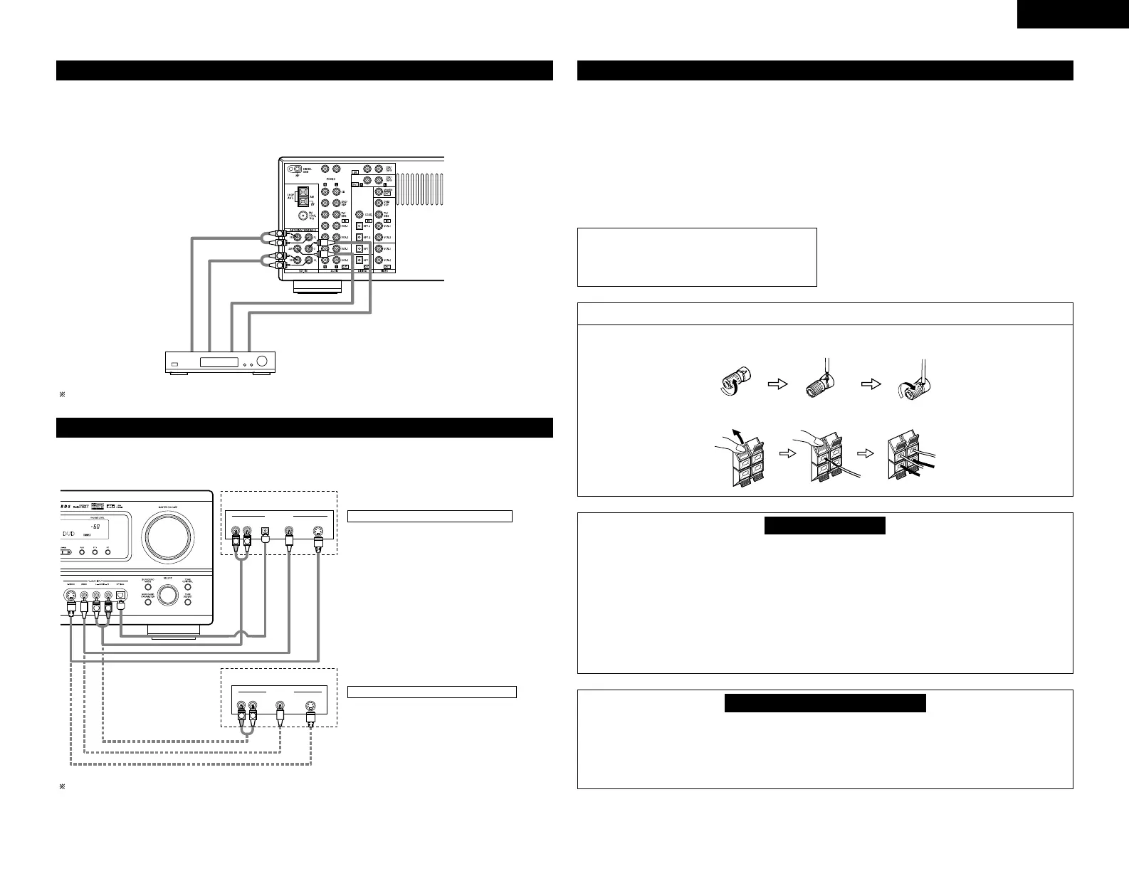
Connecting the speaker cords
1. Loosen by turning
counterclockwise.
2. Insert the cord. 3. Tighten by turning
clockwise.
Speaker system connections
• Connect the speaker terminals with the speakers
making sure that like polarities are matched ( ≈ with
≈ , √ with √ ). Mismatching of polarities will result
in weak central sound, unclear orientation of the
various instruments, and the sense of direction of
the stereo being impaired.
• When making connections, take care that none of
the individual conductors of the speaker cord come
in contact with adjacent terminals, with other
speaker cord conductors, or with the rear panel.
Protector circuit
• This unit is equipped with a high-speed protection circuit. The purpose of this circuit is to protect the
speakers under circumstances such as when the output of the power amplifier is inadvertently short-
circuited and a large current flows, when the temperature surrounding the unit becomes unusually high, or
when the unit is used at high output over a long period which results in an extreme temperature rise.
When the protection circuit is activated, the speaker output is cut off and the power supply indicator LED
flashes. Should this occur, please follow these steps: be sure to switch off the power of this unit, check
whether there are any faults with the wiring of the speaker cables or input cables, and wait for the unit to
cool down if it is very hot. Improve the ventilation condition around the unit and switch the power back on.
If the protection circuit is activated again even though there are no problems with the wiring or the
ventilation around the unit, switch off the power and contact a DENON service center.
Note on speaker impedance
• The protector circuit may be activated if the set is played for long periods of time at high volumes when
speakers with an impedance lower than the specified impedance (for example speakers with an
impedance of lower than 4 Ω/ohms) are connected. If the protector circuit is activated, the speaker output
is cut off. Turn off the set’s power, wait for the set to cool down, improve the ventilation around the set,
then turn the power back on.
1. Push the lever. 2. Insert the cord. 3. Return the lever.
Connecting the external input (EXT. IN) jacks
• These jacks are for inputting multi-channel audio signals from an outboard decoder, or a component with a
different type of multi-channel decoder, such as a DVD Audio player, or a multi-channel SACD player, or other
future multi-channel sound format decoder.
• When making connections, also refer to the operating instructions of the other components.

 Loading...