EasyManua.ls Logo

Denon AVR-1803/883 User Manual

Denon AVR-1803/883
70 pages
To Next Page IconTo Next Page
Page #1 background imageLoading...
Page #1 background image
Hi-Fi Component
SERVICE MANUAL
MODEL
AVR-1803/883
AV SURROUND RECEIVER
X0154 NC 0210
For U.S.A., Canada, Europe,
U.K., Asia, China, Hong Kong,
Taiwan R.O.C. & Korea model
Some illustrations using in this service manual are slightly different from the actual set.
16-11, YUSHIMA 3-CHOME, BUNKYOU-KU, TOKYO 113-0034 JAPAN
Telephone: 03 (3837) 5321
Question and Answer IconNeed help?

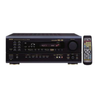
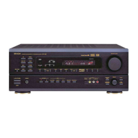
Do you have a question about the Denon AVR-1803/883 and is the answer not in the manual?

Denon AVR-1803/883 Specifications

General IconGeneral
BrandDenon
ModelAVR-1803/883
CategoryReceiver
LanguageEnglish

Summary

DENON AVR-1803/883 Service Manual

Safety Precautions

Leakage Current Check

Procedure for checking leakage current before unit return.

Specifications

Technical specifications for audio, video, tuner, and general sections.

Tuner Section Specifications

Disassembly Procedure

Level Diagrams Overview

Front, Center, Surround Level Diagram

Detailed level diagram for front, center, and surround audio channels.

Subwoofer Level Diagram

Detailed level diagram for the subwoofer audio channel.

Block Diagram

Adjustment Procedures

Tuner Section Alignment

Alignment procedures for FM and AM tuner sections.

Audio Section: Idling Current Adjustment

Idling Current Preparation

Preparation steps for adjusting the unit's idling current.

Idling Current Adjustment Steps

Detailed steps for adjusting idling current for audio channels.

Printed Wiring Board Layouts

Main P.W.B. Unit Details

CPU P.W.B. Unit Layout

CNT P.W.B. Unit Layout

Input-Preamp P.W.B. Unit Layout

DSP P.W.B. Unit Layout

Vol-Sel P.W.B. Unit Layout

P.W.B. Unit Parts List - Semiconductors & Resistors

Semiconductors Group (P.W.B. List)

List of semiconductor components for P.W.B. units.

Resistors Group (P.W.B. List)

List of resistor components for P.W.B. units.

P.W.B. Unit Resistors Group (Continued)

Capacitors Group (P.W.B. List)

List of capacitor components for P.W.B. units.

P.W.B. Unit Capacitors Group (Continued)

CPU P.W.B. Assembly - Semiconductors

CPU P.W.B. Resistors (List)

CPU P.W.B. Resistors (Continued)

CNT P.W.B. Assembly - Semiconductors

CNT P.W.B. Resistors (List)

CNT P.W.B. Resistors (Continued)

Input Volume P.W.B. Semiconductors (List)

Input Volume P.W.B. Resistors (List)

Input Volume P.W.B. Capacitors (List)

DSP P.W.B. Semiconductors (List)

DSP P.W.B. Resistors (List)

DSP P.W.B. Resistors (Continued)

Voltage-Sel. P.W.B. Assembly - Other Parts

Exploded View and Parts List

Exploded View Illustration

Visual representation of the unit's assembly with numbered parts.

Exploded View Parts List

List of parts corresponding to the exploded view illustration.

Exploded View Parts List Breakdown

Main P.W.B. Assy Parts (Continued)

Wiring Diagram

Schematic Diagrams (1/10): Input B'D

Schematic Diagrams (2/10): DSP Unit

Schematic Diagrams (3/10): Connection B'D

Schematic Diagrams (4/10): Main B'D

Schematic Diagrams (5/10): CPU B'D

Schematic Diagrams (6/10): Video & D-Video Unit

Schematic Diagrams (7/10): Comp-Video Unit

Schematic Diagrams (8/10): D-Video & Surround Back

Schematic Diagrams (9/10): Front Board

Schematic Diagrams (10/10): Tuner B'D

Related product manuals