19
AVR-4802/AVC-A11SR
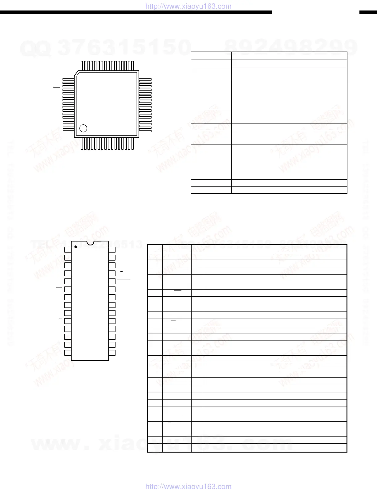
LC75721E (IC102)
AD1854 (IC301, 303, 305, 307)
64
49
48 33
32
17
161
AM 1
AM 2
AM 3
AM 4
AM 5
AM 6
AM 7
AM 8
AM 9
AM 10
AM 11
AM 12
AM 13
AM 14
AM 15
AM 16
AM 17
AM 18
AM 19
AM 20
AM 21
AM 22
AM 23
AM 24
AM 25
AM 26
AM 27
AM 28
AM 29
AM 30
AM 31
AM 32
G7
G8
G9
G10
G11
AA8/G12
AA7/G13
AA6/G14
AA5/G15
AA4/G16
AA3
AA2
AA1
AM35
AM34
AM33
DI
CL
CE
RES
V
DD
OSCI
OSCO
Vss
TEST
V
FL
G1
G2
G3
G4
G5
G6
1
2
3
4
5
6
7
8
9
10
11
12
13
14
28
27
26
25
24
23
22
21
20
19
18
17
16
15
DGND
MCLK
CLATCH
CCLK
CDATA
384/256
X2MCLK
ZEROR
DEEMP
96/48
AGND
OUTR+
OUTR
-
FILTR
DVDD
SDATA
BCLK
L/RCLK
PD/RST
MUTE
ZEROL
IDPM0
IDPM1
FILTB
AVDD
OUTL+
OUTL
-
AGND
Name Function
Terminal Function
No.
1 DGND I Digital Ground
2 MCLK I Master Clock Input
3 CLATCH I Latch input for control data
4 CCLK I Control clock input for control data
5 CDATA I Serial control input
6 384/256 I Selects the master clock mode
7 X2MCLK I Selects internal clock doubler (LO) or internal clock=MCLK (HI)
8 ZEROR O Right Channel Zero Flag Output
9 DEEMP I De-Emphasis
10 96/48 I Selects 48kHz (LO) or 96kHz Sample Frequency Control
11,15 AGND I Analog Ground
12 OUTR+ O Right Channel Positive line level analog output
13 OUTR- O Right Channel Negative line level analog output
14 FILTR O Voltage Reference Filter Capacitor Connection
16 OUTL- O Left Channel Negative line level analog output
17 OUTL+ O Left Channel Positive line level analog output
18 AVDD I Analog Power supply
19 FILTB O Filter Capacitor connection
20 IDPM1 I Input serial data port mode control one
21 IDPM0 I Input serial data port mode control zero
22 ZEROL O Left Channel Zero Flag output
23 MUTE I Mute. Assert HI to mute both stereo analog output
24 PD/RST I Power-Down/Reset
25 L/R CLK I Left/Right clock input for input data
26 BCLK I Bit clock input for input data
27 SDATA I Serial input
28 DVDD I Digital Power Supply
I/O
Terminal Function
Symbol Function
VDD Power terminal +5V
Vss Power terminal GND
VFL Power terminal FL drive
Serial data transfer terminal
DI DI: Data
CL CL: Clock
CE CE: Chip enable
OSCI
External CR connecting terminal
OSCO
RES System reset terminal
AM1 ~ AM35
Anode output terminal
AA1 ~ AA3
AA4/G16
Anode/Grid output terminal
AA5/G15
AA6/G14
AA7/G13
AA8/G12
G1 ~ G11 Grid output terminal
TEST LSI test terminal
w
w
w
.
x
i
a
o
y
u
1
6
3
.
c
o
m
Q
Q
3
7
6
3
1
5
1
5
0
9
9
2
8
9
4
2
9
8
T
E
L
1
3
9
4
2
2
9
6
5
1
3
9
9
2
8
9
4
2
9
8
0
5
1
5
1
3
6
7
3
Q
Q
TEL 13942296513 QQ 376315150 892498299
TEL 13942296513 QQ 376315150 892498299
http://www.xiaoyu163.com
http://www.xiaoyu163.com
 Loading...