13
AVR-5308CI / AVC-A1HD
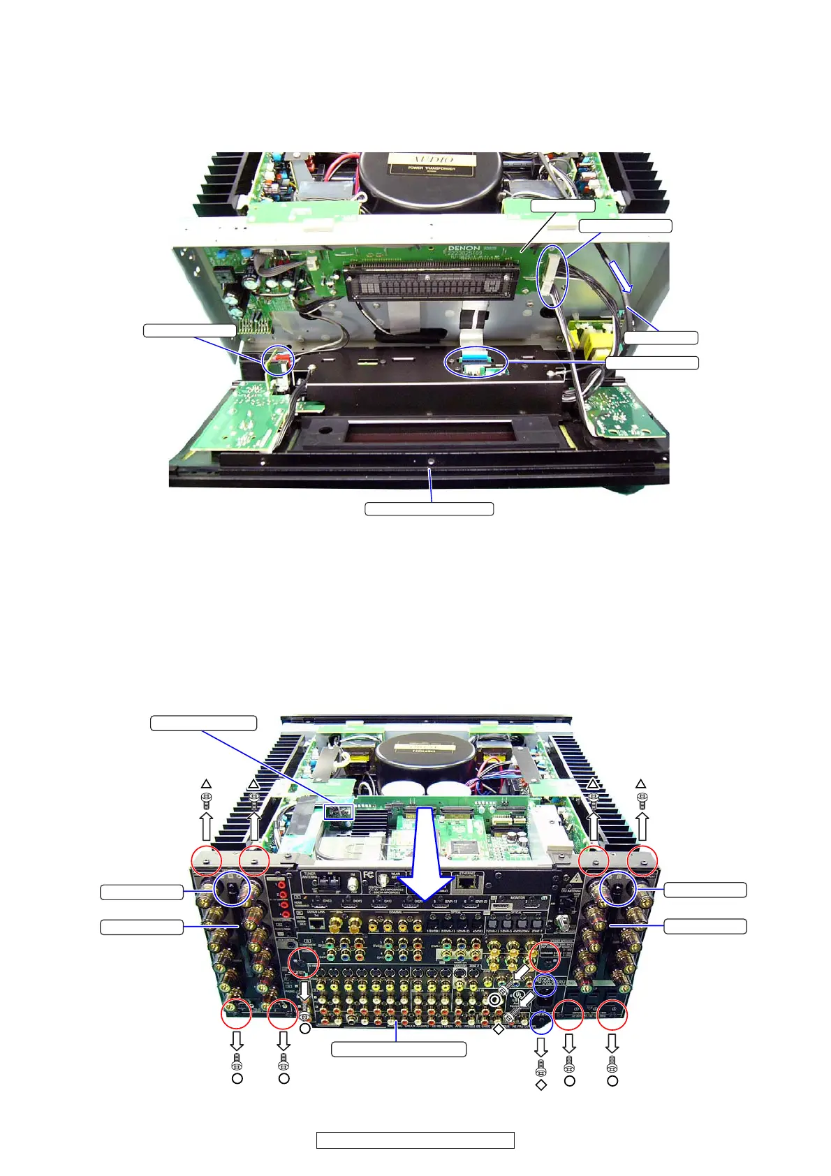
(5) Draw the 5P-shield wire in the arrow direction.
(6) Disconnect the CX134,CX802 connector on the 1U-
3825-1 : FLD UNIT.
(7) Disconnect FFC cable.
(8) Disconnect VH connector for Power switch. Detach
the FRONT PANEL Ass’y.
6. BACK PANEL ASS’Y
(1) Remove 4 screws △ of top side.
(2) Disconnect the Wire connector.
(3) Remove 2 Push Rivet. Detach the Screw Cover.
(4) Remove screw of the backside of Screw Cover. (Refer
to the following page.)
(5) Remove 6 screws ○ fixing the Back Panel.
(6) Remove 2 screws ◇ fixing the AC INLET.
(7) Draw BACK PANEL Ass’y slowly.
VH wire
FRONT PANEL Ass'y
5P-Shield wire
CX134,CX802
FFC cable
1U-3825-1
Wire connector
Push Rivet
Push Rivet
Screw Cover
Screw Cover
BACK PANEL Ass'y
(5) 5P シールドワイヤーを矢印方向に引き出します。
(6) 1U-3825-1:FLDUNIT のコネクター (CX134,CX802)
をはずします。
(7) FFC ケーブルをはずします。
(8) 電源スイッチの VH コネクターをはずして FRONT
PANELAss'y をはずします。
6. BACKPANELASS'Y
(1) △ねじ 4 本をはずします。
(2) WireConnector をはずします。
(3) PushRivet を 2ヶ所はずし、ScrewCover を取り外し
ます。
(4) 次ページを参考に ScrewCover の裏側のねじをはず
します。
(5) ○ねじ 6 本をはずします。
(6) ACINLET の◇ねじ 2 本をはずします。
(7) BACKPANELAss'y をゆっくり引き出します。
 Loading...