When the results of check item (46) are "00"
(Detection of 5V is not OK.)
When the results of check item (47) are "00 or 04"
(If the DDC are not OK)
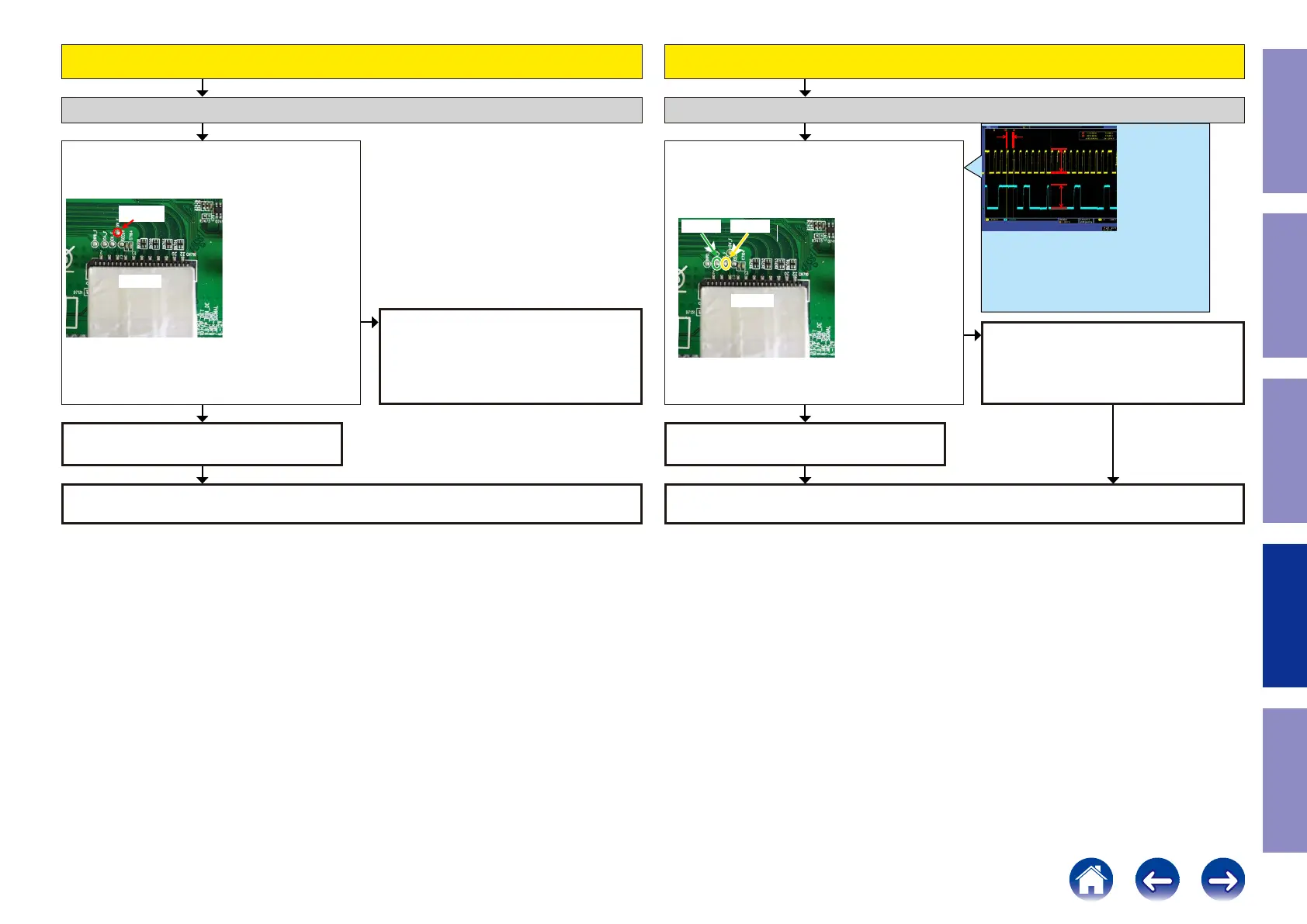
Check item(48). Check the +5V voltage.
Does "+5 V" at the following test point indicate 5 V?
The test points are as follows. (HDMI SW[IC701]
CN710
+5V_F
Check item(49). Check the DDC line :
Does "DDCCL" and " DDCDA" signal of the HDMI SW
[IC701] indicate 5 V?
The test points are as follows.
CN710
CK_F DA_F
Check the +5V voltage. (Front HDMI Buffer) Check the DDC Line. (Front HDMI Buffer)
HDMI SW [IC701] is faulty.
Replace with a new device.
Recheck from check item (2).
If it does not work, replace the PCB.
Recheck from check item (2).
If it does not work, replace the PCB.
HDMI SW [IC701] is faulty.
Replace with a new device.
Check for a short circuit in the 5 V line, the
Front HDMI FFC, and the 5V Switch [IC733].
If there is no problem, the HDMI SW1[IC701]
or 5VSwitch[IC733] is faulty.
Replace with a new device.
Check for a short circuit in the DDC line and
check the Front HDMI FFC.
If there is no problem, the Front HDMI Buffer
[IC811] is faulty.
Replace with a new device.
YESYES
NO
NO
less than 100KHz
5V
5V
This diagram shows an example of the DDC commu-
nication waveform.
-The high level voltage is 5V.
-The frequency of the DDC CLK is 100 KHz or less.
Check at each test point.
Voltage scale:2.0V/div
Time scale:40us/div
97
Caution in
servicing
Electrical Mechanical Repair Information Updating
 Loading...