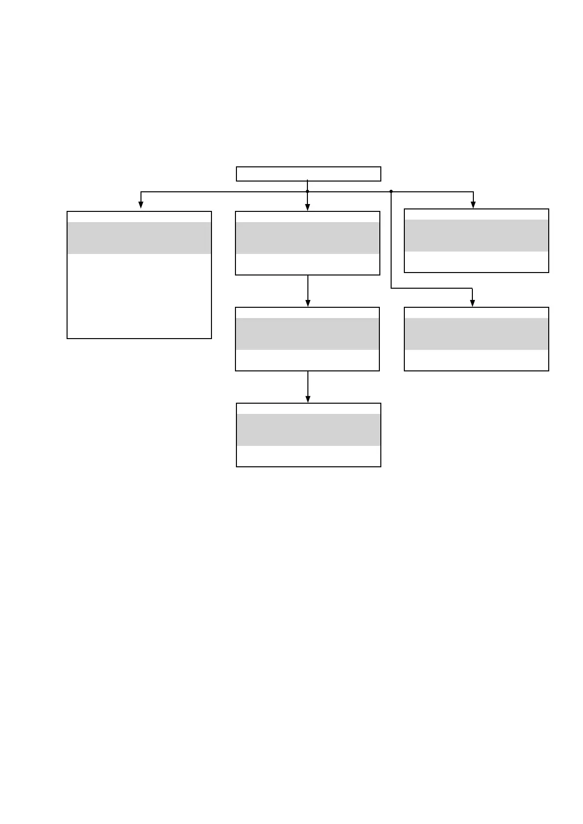
FRONT PANEL ASSY
See "DISASSEMBLY"
1. FRONT PANEL ASSY
and "EXPLODED VIEW"
FRONT PCB
Ref. No. of EXPLODED VIEW:P1
USB & MIC PCB
Ref. No. of EXPLODED VIEW:P4
STNDBY PCB
Ref. No. of EXPLODED VIEW:P2
PHONE PCB
Ref. No. of EXPLODED VIEW:P3
TOP COVER
TRANS
See "DISASSEMBLY"
7. TRANS
and "EXPLODED VIEW"
POWER TRANS
Ref. No. of EXPLODED VIEW: P15
VIDEO&OPTICAL PCB
See "DISASSEMBLY"
2. VIDEO&OPTICAL PCB
and "EXPLODED VIEW"
VIDEO PCB
Ref. No. of EXPLODED VIEW:P10
DIGITAL PCB
See "DISASSEMBLY"
3. DIGITAL PCB
and "EXPLODED VIEW"
DIGITAL PCB
Ref. No. of EXPLODED VIEW:P8
MAIN PCB
See "DISASSEMBLY"
4. MAIN PCB
and "EXPLODED VIEW"
MAIN PCB
Ref. No. of EXPLODED VIEW:P6
SMPS PCB
See "DISASSEMBLY"
6. SMPS PCB
and "EXPLODED VIEW"
SMPS PCB
Ref. No. of EXPLODED VIEW:P12
DISASSEMBLY
• Remove each part following the ow below.
• Reassemble the removed parts in the reverse order.
• Read "Precautions During Work" before reassembling the removed parts.
• If wire bundles are removed or moved during adjustment or part replacement, reshape the wires after completing the
work. Failure to shape the wires correctly may cause problems such as noise.
15

 Loading...