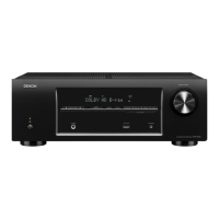
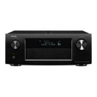
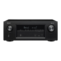
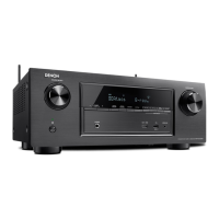
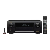
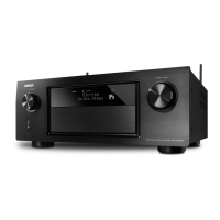
Do you have a question about the Denon AVR-X500 and is the answer not in the manual?
Receiver type | - |
---|---|
Frequency range | 10 - 100000 Hz |
Pre-out channels | 1 SW |
Speaker selector | No |
Input sensitivity | 200 mV |
Pre-out connectivity | Yes |
Audio output channels | 5.1 channels |
Signal-to-Noise Ratio (SNR) | 98 dB |
Total Harmonic Distortion (THD) | 0.08 % |
Power output per channel (1KHz@6 Ohm) | 140 W |
Power output per channel (20-20KHz@8 Ohm) | 75 W |
HDMI in | 4 |
Audio (L/R) in | 3 |
Composite video in | 2 |
Ethernet LAN (RJ-45) ports | 0 |
Number of HDMI outputs | 1 |
Connectivity technology | Wired |
Speakers connectivity type | Clamp terminals |
Multichannel pre out connectivity | RCA |
FM band range | 87.5 - 108 MHz |
Supported radio bands | AM, FM |
Product color | Black |
Audio decoders | Dolby Digital EX, Dolby Pro Logic IIx, Dolby TrueHD, DTS 96/24, DTS-ES, DTS-HD Master Audio |
Apple docking compatibility | Not supported |
Number of products included | 1 pc(s) |
AC input voltage | 230 V |
AC input frequency | 50 Hz |
Power consumption (standby) | 0.3 W |
Power consumption (typical) | 330 W |
Cables included | AC |
Depth | 319 mm |
---|---|
Width | 434 mm |
Height | 151 mm |
Weight | 7900 g |
Explains how to navigate and search within the service manual using Adobe Reader features.
Details various Adobe Reader tools for magnifying diagrams, including zoom, pan, and loupe.
Guides on configuring print settings for specific manual sections.
Instructions on using the 'Sign' function to add personal annotations to the manual.
Details the process for checking leakage current before returning the set to the customer.
Provides essential cautions regarding electric shock, disassembly, part usage, and wiring.
Outlines critical safety checks to perform after completing service or repairs.
Explains critical part warnings and notation for resistance/capacitance values.
Provides guidance on part availability, ordering, and identification marks.
Details audio, tuner, video, and general specifications of the AV receiver.
Displays the physical dimensions and weight of the AV receiver.
Explains the procedure for initializing the AV receiver, typically after component replacement.
Provides details and part numbers for a service jig used for firmware updates.
Covers removal of the top cabinet and front panel assembly.
Details disassembly of the digital PCB and radiator assemblies.
Covers removal of standby PCB, regulator PCB, and trans power unit.
Explains how to activate special modes by pressing specific buttons on the unit.
Describes how to display firmware versions of µcom, DSP, and OSD.
Details the procedure for initializing the unit's backup data, clearing settings.
Describes how to access a mode to view the unit's protection history and error codes.
Details checks required when replacing the microprocessor or flash ROM, noting software writing needs.
Lists necessary items and PC/receiver connections for performing a firmware upgrade.
Guides on clicking the setup folder and running the flash loader demonstration executable file.
Details connecting the AV receiver to the WRITING KIT and initiating the flash loader software.
Guides on configuring the WRITING KIT and loading the DSP1 firmware file.
Guides on configuring the WRITING KIT and loading the DSP2 firmware file.
Guides on configuring the WRITING KIT and loading the OSD firmware file.
Guides on configuring the WRITING KIT and loading the MAIN firmware file.
Explains unit initialization, notices, and confirming the firmware version after the update.
Procedure for adjusting idling current in the audio section using a DC voltmeter.
Outlines preparations and steps for adjusting VR510 and other variable resistors for correct voltage levels.
Explains symbols and lists adjustable surround parameters for different modes.
Lists surround parameters that can be adjusted per channel and per surround mode.
Shows default and selectable surround modes based on input signal type and format.
Diagnoses and resolves issues where the unit does not power on or has blown fuses.
Guides through diagnosing analog video output problems by checking voltages and inputs.
Provides a flowchart to resolve issues with no picture or sound from HDMI/DVI connections.
Addresses HDMI recognition, signal issues, and output circuitry diagnosis.
Guides on checking analog and digital audio outputs, including block diagrams.
Provides a flowchart to troubleshoot no sound output, focusing on power transistors and related components.
Shows example waveforms and identifies test points in the digital block.
Illustrates signal flow for analog/video and power supply distribution.
Illustrates signal levels for front, center, surround, and subwoofer channels.
Shows the interconnection of major PCBs and components via various cables and connectors.
Provides an exploded view illustrating the physical assembly of the unit's components.
Highlights critical parts that require specific replacement parts as recommended by the manufacturer.
Provides notes on parts marked 'nsp', '*' and clarifies that listed parts are for maintenance only.
Lists semiconductors, resistors, capacitors, and other parts for Front, Main, Digital, and Power PCBs.
Lists component assemblies, screws, and wires with reference numbers.
Lists packaging materials and included accessories like cords and manuals.