10
DISASSEMBLY
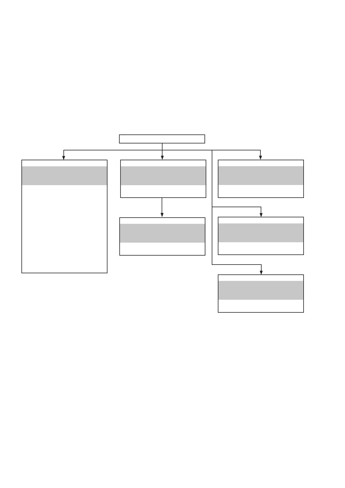
• Disassembleinorderofthearrowinthefollowinggure.
• Inthecaseofthere-assembling,assembleitinorderofthereverseofthefollowingow.
• Inthecaseofthereassembling,observe"Cautionconcerningdisassemblyandassembly!".
• Ifwirebundlesareuntiedormovedtoperformadjustmentorreplacepartsetc.,besuretorearrangethemneatlyas
theywereoriginallybundledorplacedafterward.
Otherwise, incorrect arrangement can be a cause of noise generation.
FRONTPANELASSY
Refer to "DISASSEMBLY
1.FRONTPANELASSY"
and
"EXPLODEDVIEW"
FRONTPCB
(Ref.No.ofEXPLODEDVIEW:C1)
POWERKNOBPCB
(Ref.No.ofEXPLODEDVIEW:C1-1)
HEADPHONEPCB
(Ref.No.ofEXPLODEDVIEW:C1-2)
PORTABLEPCB
(Ref.No.ofEXPLODEDVIEW:C1-3)
USBPCB
(Ref.No.ofEXPLODEDVIEW:C1-4)
FRONTHDMICABLEPCB
(
Ref.No.ofEXPLODEDVIEW:C1-5)
F-HDMIPCB
(Ref.No.ofEXPLODEDVIEW:C3-1)
RADIATOR ASSY
Refer to "DISASSEMBLY
3. RADIATOR ASSY"
and
"EXPLODEDVIEW"
MAINPCB
(Ref.No.ofEXPLODEDVIEW:C2)
STANDBYPCB
Refer to "DISASSEMBLY
4.STANDBYPCB"
and
"EXPLODEDVIEW"
STANDBYPCB
(Ref.No.ofEXPLODEDVIEW:C4)
REGULATORPCB
Refer to "DISASSEMBLY
5.REGULATORPCB"
and
"EXPLODEDVIEW"
REGULATORPCB
(Ref.No.ofEXPLODEDVIEW:C5)
TRANSPOWER
Refer to "DISASSEMBLY
6.TRANSPOWER"
and
"EXPLODEDVIEW"
TRANSPOWER
(Ref.No.ofEXPLODEDVIEW:C6)
DIGITALPCBASSY
Refer to "DISASSEMBLY
2.DIGITALPCBASSY"
and
"EXPLODEDVIEW"
DIGITALPCB
(Ref.No.ofEXPLODEDVIEW:C3)
TOPCABINET

 Loading...