Explanatory Photos for DISASSEMBLY
• For the shooting direction of each photos used in this manual, see the photo below.
• A, B, C and D in the photo below indicate the shooting directions of photos.
• The photographs with no shooting direction indicated were taken from the top of the unit.
• Photos of AVR-S510BT E3 are used in this manual.
The viewpoint of each photograph
(Shooting direction:X)[View from the top]•
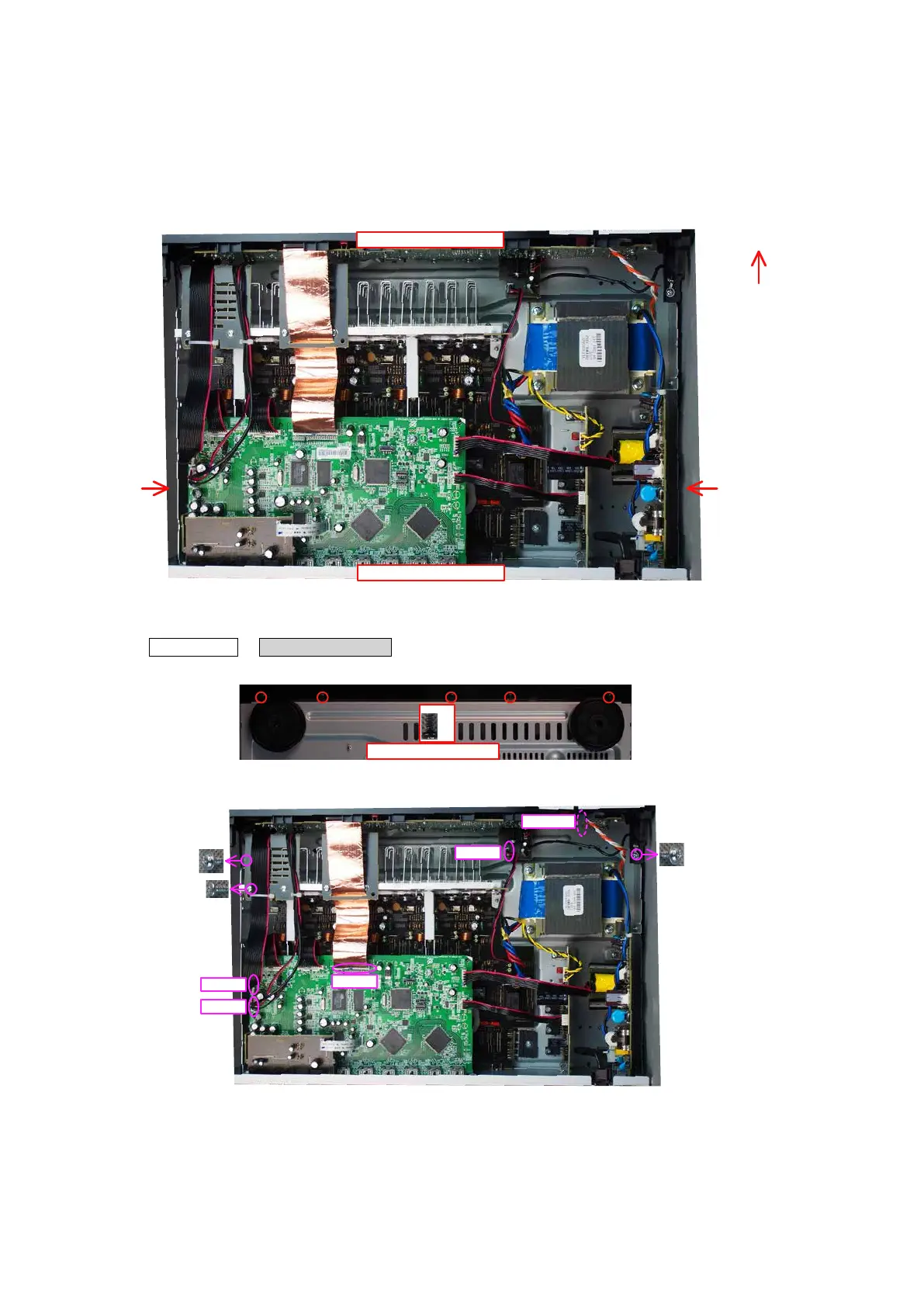
1. FRONT PANEL ASSY
Proceeding: TOP COVER
→
FRONT PANEL ASSY
(1) Remove the screws.
(2) Remove the screws. Remove the connector wires and FFC.
Front side
Shooting
direction: D
Shooting
direction: C
↑Shooting direction: A↑
↓Shooting direction: B↓
View from the bottom
x5
FFC
CN713
CN752
CN102
CN104
16

 Loading...