EN5339QI
�Enpirion 2012 all rights reserved, E&OE www.enpirion.com, Page 2
���������������������
Part Number Package Markings Temp Rating (°C) Package Description
EN5339QI EN5339 -40 to +85 24-pin (4mm x 6mm x 1.1mm) QFN T&R
EN5339QI-E EN5339 QFN Evaluation Board
Packing and Marking Information: http://www.enpirion.com/resource-center-packing-and-marking-information.htm
���������������������������
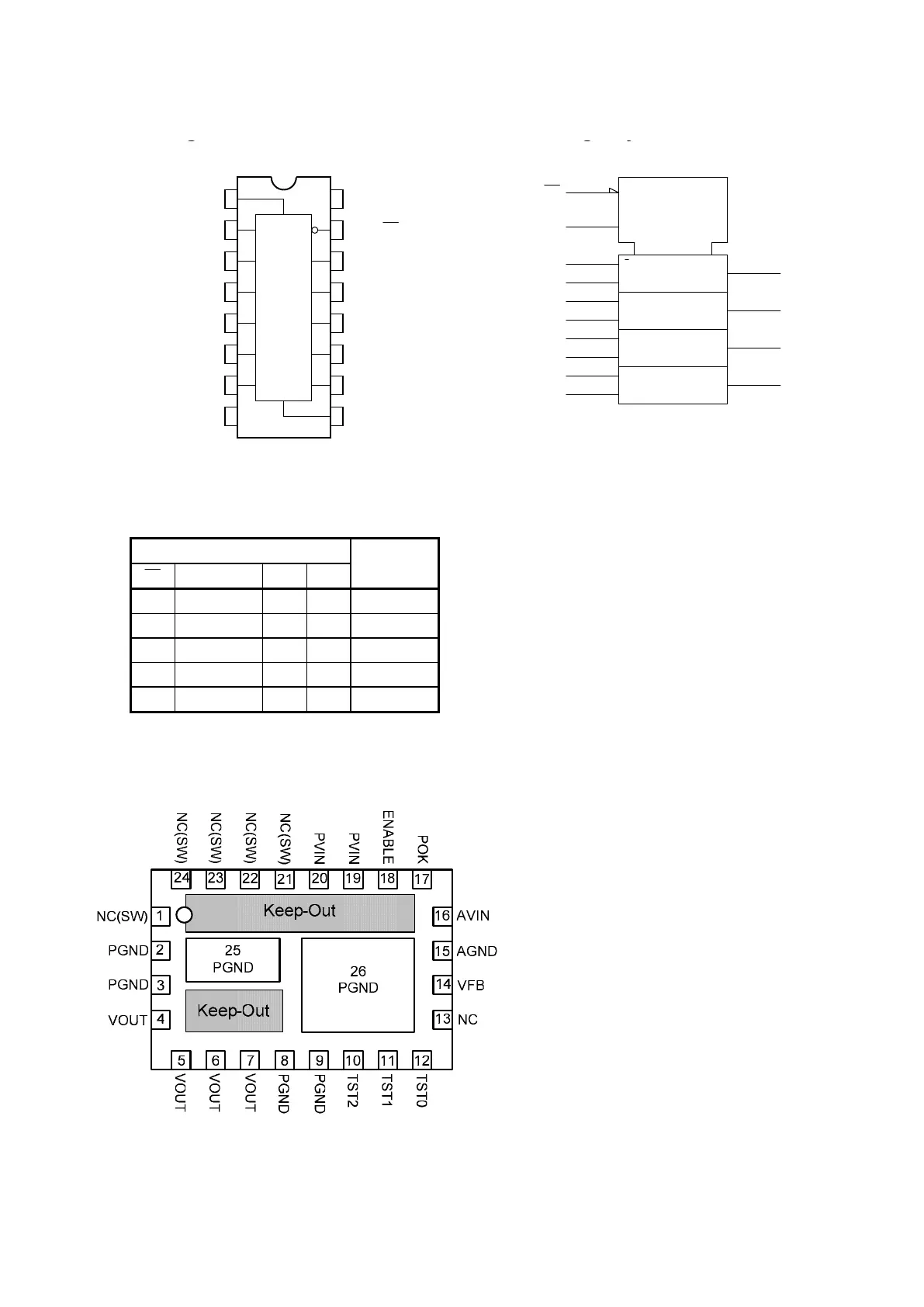
Figure 3: Pin Out Diagram (Top View)
NOTE A: NC pins are not to be electrically connected to each other or to any external signal, ground, or voltage.
However, they must be soldered to the PCB. Failure to follow this guideline may result in part malfunction or damage.
NOTE B: Grey area highlights exposed metal on the bottom of the package that is not to be mechanically or electrically
connected to the PCB. There should be no traces on PCB
top layer under these keep out areas.
NOTE C: White ‘dot’ on top left is pin 1 indicator on top of the device package.
����������������
1, 21-24 NC(SW)
NO CONNECT: These pins are internally connected to the common switching node of the
internal MOSFETs. They must be soldered to PCB but not be electrically connected to any
external signal, ground, or voltage. Failure to follow this guideline may result in device
damage.
2-3, 8-9 PGND
Input and output power ground. Connect these pins to the ground electrode of the input and
output filter capacitors. See VOUT, PVIN descriptions and Layout Recommendation
for more
details.
4-7 VOUT
Regulated converter output. Connect to the load and place output filter capacitor(s) between
these pins and PGND pins 7 and 8. See layout recommendation for details
10 TST2 Test Pin. For Enpirion internal use only. Connect to AVIN at all times.
11 TST1 Test Pin. For Enpirion internal use only. Connect to AVIN at all times.
 Loading...