JIG FOR SERVICING
Use the following jigs (extension cable kit) when repairing the PCBs.
Order with your dealer for the jigs your dealer if necessary.
CAUTION : Incorrect connections may cause malfunction.
Connection of Jig for DIGITAL PCB
---Items to Be Prepared---
8U-110084S : EXTENSION UNIT KIT : 1 Set
Insulation sheet (Not supplied) : 1 sheet
Ground lead (Not supplied) : 1 pc
-Proceeding-
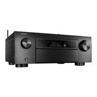
(1) Remove the screws.
(2) Remove the connector PCB.
↑Shooting direction: A↑
x10
N6012
N6014
(3) Remove the DIGITAL PCB from the chassis and turn it over.
Place an insulation sheet larger than the PCB underneath the DIGITAL PCB.
b
Connect the earth of the PCB to the chassis using an earth wire, etc.
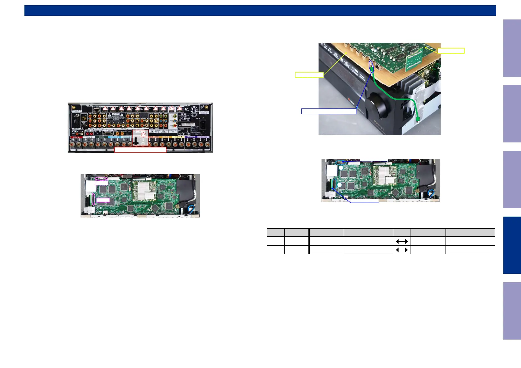
(4) Connect the expansion cables.
Board-to-Board Connections
No. Pin Ref. No. PCB Ref. No. PCB
q
33pin N5204 CONNECT-3
N6014 DIGITAL
w
33pin N5907 CONNECT-1
N6012 DIGITAL
PCB INPUT
Insulation sheet
CHASSIS-HDMI CONNECTOR
1
2
CONNECTOR-3
CONNECTOR-1
Before Servicing
This Unit
Electrical Mechanical Repair Information Updating
190
 Loading...