Explanatory Photos for DISASSEMBLY
• Fortheshootingdirectionofeachphotosusedinthismanual,seethephotobelow.
• A, B, C and Dinthephotobelowindicatetheshootingdirectionsofphotos.
• Thephotographswithnoshootingdirectionindicatedweretakenfromthetopoftheunit.
• PhotosofAVR-X6500HE3areusedinthismanual.
The viewpoint of each photograph
(Shootingdirection:X)[Viewfromthetop]
↓Shooting direction: C↓
↑Shooting direction: D↑
↑Shooting direction: A↑
↓Shooting direction: B↓
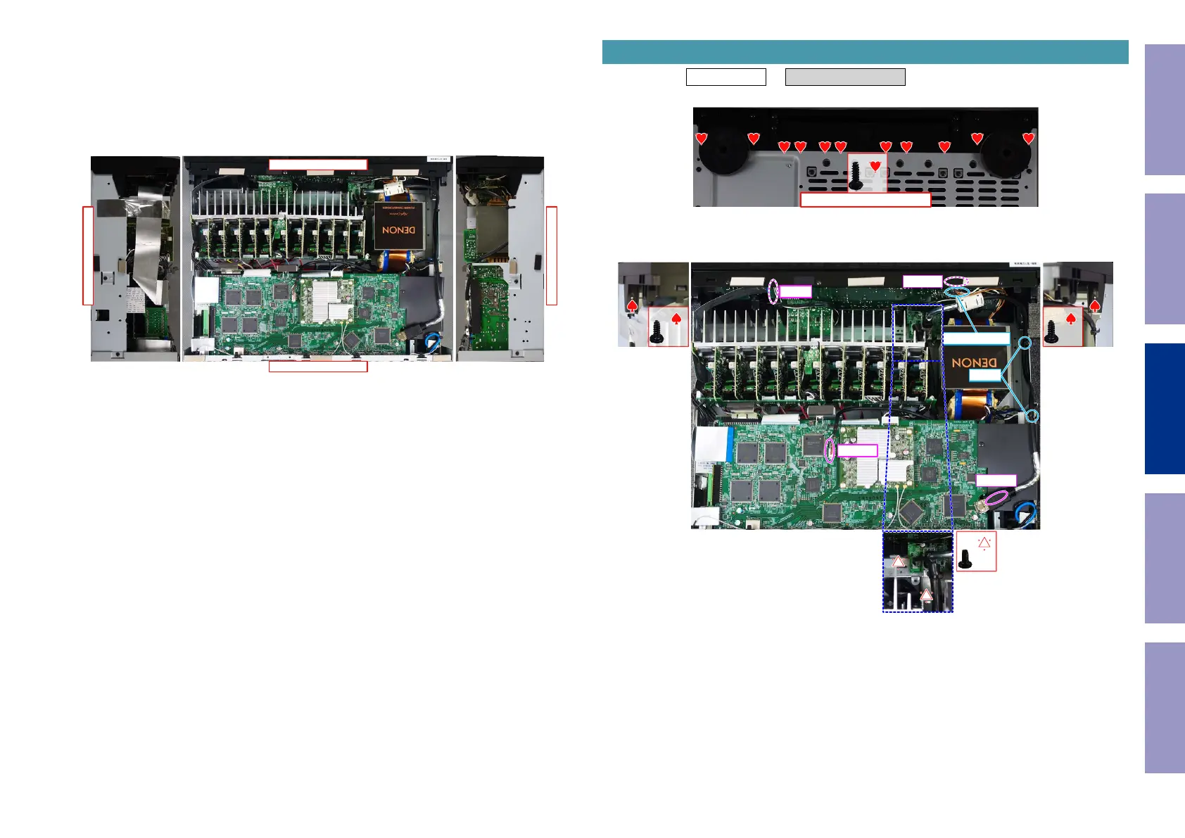
Proceeding : TOP COVER → FRONT PANEL ASSY
(1) Removethescrews.
(2) Removethescrews.RemovetheSTYLEPINandconnectors.RemovetheFFC.
1. FRONT PANEL ASSY
View from the bottom
x11
x1 x1
x2
N6401
FFC
N8001
N3403
CUT
STYLE PIN
Before Servicing
This Unit
Electrical Mechanical Repair Information Updating
77
 Loading...