Use a jig to extend the DIGITAL PCB
A
Check the power supply voltage.
AUDIO/VIDEO PCB
V+3.3V : C3748 +
q
V-5V : C3749 -
w
Check of the I2C control signal for video selector IC
[U3703].
CONNECT-2 PCB
I2C(SCL) : C3732
e
I2C(SDA) : C3733
r
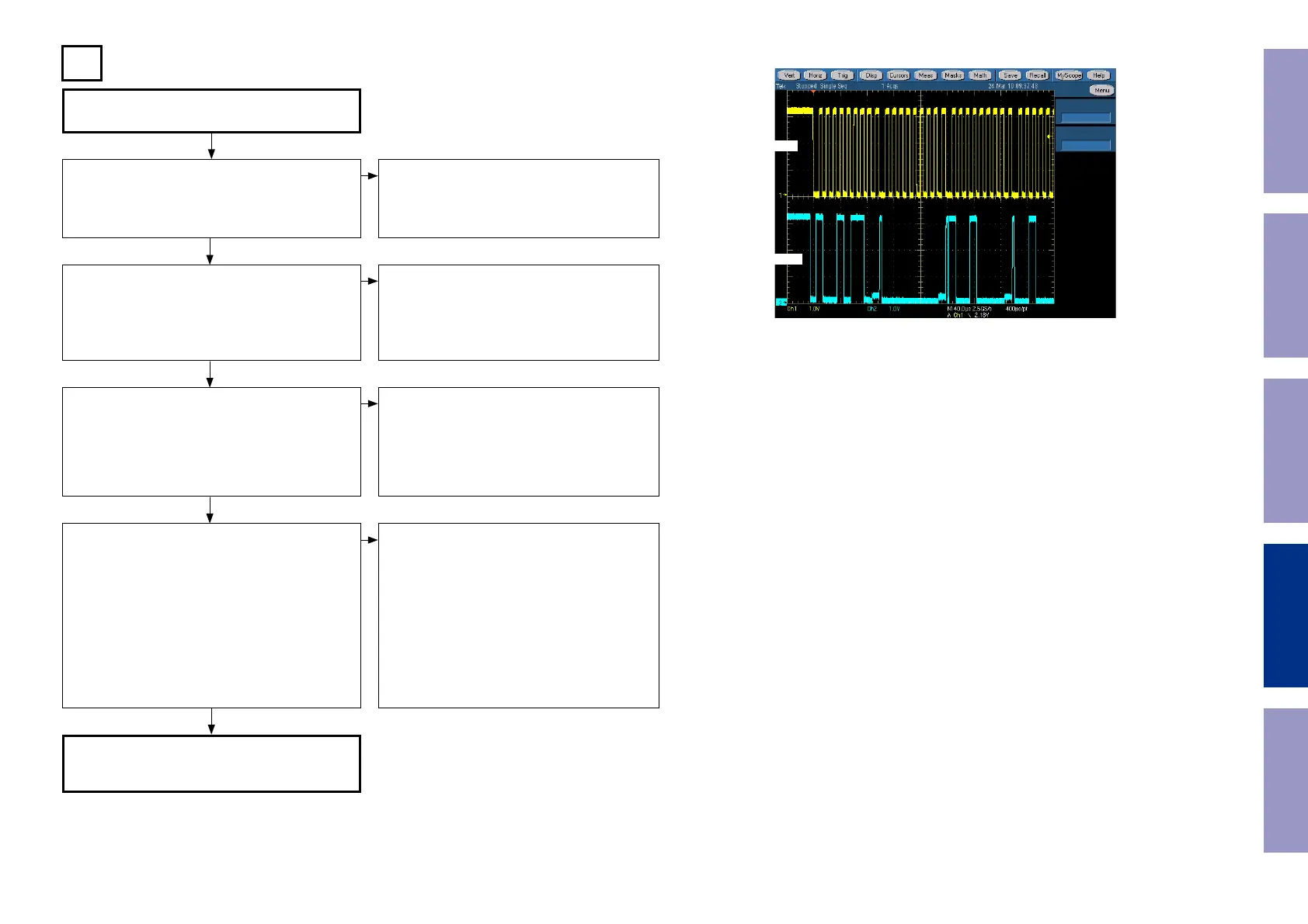
See the sample waveform
Does the signal input to the video selector IC
[U3703]?
V : C3714
t
Component-Y : C3705
y
Component-Cb : C3706
u
Component-Cr : C3707
i
Does the signal output from the video selector IC
[U3703]?
V (to Monitor out) : R3740
o
V (to Z2 Monitor out) : R3731
Q0
V (to DIGITAL PCB) : R3736
Q1
Component-Y (to Monitor out) : R3742
Q2
Component-Cb (to Monitor out) : R3746
Q3
Component-Cr (to Monitor out) : R3750
Q4
Component-Y (to DIGITAL PCB) : R3744
Q5
Component-Cb (to DIGITAL PCB) : R3748
Q6
Component-Cr (to DIGITAL PCB) : R3752
Q7
FFC connection error or contact failure. [N9018]
Power IC [U3701] failure (V-5V).
DIGITAL PCB DV+3.3V, DV5V
FFC connection error or contact failure.
DIGITAL PCB faulty.
Input terminal [K3503 / K3501] faulty, or a fault
occurs between video select IC [U3703].
Video select IC [U3703] is faulty.
Output terminal [K3503 or K3505] faulty.
TV monitor connection error or contact failure.
q
w
e
r
NO
NO
NO
NO
YES
YES
YES
YES
I2C communication wave form (sample)
CLK
DATA
Before Servicing
This Unit
Electrical Mechanical Repair Information Updating
85
 Loading...